Tuesday, 13 October 2015

Switching

Approaches for Moving Data In a Network

Till now we have discussed about the Basics of Computer Networks , Mediums to transfer Data and The Types of Delays in Computer Networks. In this post, I am going to tell you about the approaches or the techniques that are used for moving data in a Computer Network.

There are basically two approaches for moving data from Source host to the Destination Host. These are:
1. Circuit Switching
2. Packet Switching


CIRCUIT SWITCHING

In Circuit Switching, before the two hosts start communicating , the resources along the path are to be reserved, that are needed by the two hosts for their communication. The Resources are reserved for as long as the two hosts communicate.

Now I should give a live example that will make circuit switching clear to you.

Let us suppose that there are 2 restaurants A and B. In restaurant A, there is a need to reserve a table before going there for dinner or lunch. Whereas in restaurant B, there is no need for reservation. Now before going to restaurant A, you have to make a call and reserve a table but when you will arrive there, the table is set for you and you can directly be seated and order your meal. But in restaurant B, you need not bother to reserve a table, but when you arrive at the restaurant, you might have to wait for a table to get free before you can be seated.

In this restaurant analogy, restaurant A uses circuit switching for the customers.

circuit switched networks, minimal delay, resources reserved, telephones


A very classic example of circuit switching is your Landlines or telephones. When you make a call to your friend, a connection is established between both of you. And this connection remains open till the time you both are contacting and don't put your phone down. Since all the resources are reserved by you for that network, you can send and receive data at a very constant transmission rate.

Circuit Switched Networks are used for voice and video calls where any delay in the call can make a huge difference. Another example of circuit switched networks is Skype, for video calling.

Advantages of Circuit Switched Networks

1. Dedicated connection is established, the delays in the communication are very less or almost nil.

2. The quality of the connection or the call is very high.


Disadvantages of Circuit Switched Networks

       1. Now say, on telephone you talk to your friend for 15 min. But between these 15 min. , you remain quiet for 5 min., while still holding the phone in your hand. Thus, for those 5 min., the resources are misused and get wasted.
  
       2. It is not a good option for networks, where the traffic is very high. Because if two hosts reserve the resources, the other hosts have to wait for that period to leave those resources. Resulting in huge delays. In simple words, we can say that, circuit switching is not suitable for bursty traffic networks.

  • For circuit switched networks, there are various multiplexing techniques that are being used, in order to increase bandwidth utilisation. I will tell you about the different multiplexing techniques in the later posts.


PACKET SWITCHING
In Packet Switching, instead of reserving the resources, the packets are being send on the demand phenomenon. For example, if a host A has to send a packet to host B through a communication link or router, but that link is over-flow or is full, then the packet has to wait in the queue, to get transmitted.
Packet Switching is a dynamic phenomenon, that uses the resources only when needed.
packet switched networks, optimum bandwidth utilisation,  no resource wasted,


Advantages of Packet Switching

The resources or the bandwidth is optimally utilised without any wastage.

Disadvantages of Packet Switching

       1.The packets can arrive in a wrong order as they were sent.
        
       2. The delays between different packet can be different, resulting in degradation of the service provided.

Therefore, it all depends on the Application Developer, which Switching technique he wants to use. In today's Internet, as the Traffic is so huge, so Packet Switching is used in Internet Services.

Wifi

Design Your Wi-Fi LAN

You can yourself form a Wi-Fi LAN and access it with in your home or office. Wi-Fi  LAN's now a days are used to play multi-player games, to access internet from a host in different hosts and to exchange files with different computers.

Here it is step by step explanation, how to set-up your own LAN, that to without any wire or cable.

Step 1: Switch on your WI-FI plug in your laptop.

Step 2:  Go to your Control Panel and then go to "Network and Internet" and then to "Network and Sharing Centre".

Step 3: Click on "Set up a new connection or network".

design wi-fi lan, control panel, computer, connection, computer network


Step 4: Click on "Set-up a wireless ad hoc (computer-to-computer) network" and click "Next" and again "Next".


Step 5: Then you can give your network a name. Say "XYZ". If you want that only your authorised users can connect to your network whom you want to connect, then select Security Type as "WPA-2- Personal". Otherwise select it as "No Authentication  (Open)". Then anyone can connect to it who is in the range of your network.


Step 6: Then Click "Next.

Step 7: Now your network is ready and connect it with others. just one click away.

Step 8: Now you have to switch on your network. Go to the network icon in the right of the taskbar of your system.
 You can see your networks name there, that you just created. Click on it and click "Connect".


Now others can switch on the Wi-Fi in their devices and connect with your network.

I am done with it. Its all that I have in this topic.


Networking


Twisted Pair Wires, Graham bell, communication, computer network, technology,

Different Types Of Communication Mediums In Networks

The Communication Medium plays an important role in Networks. If the medium works well and properly, then the speed of transferring data is good but if the medium is not working properly, then your data would be delayed or would not be sent or even can be lost during transmission. In Computer Networks, we call this speed of transmitting data, as DATA RATE.

There are two types of networks that you can set-up.
1. Wired Network
2. Wireless Network

1. WIRED NETWORK: 
The Wired network is mostly set-up using an Ethernet Cable. This can be done using 3 technologies.

i) Twisted Pair Wires: 

This technology was invented by Alexander Graham Bell. These wires are the most oldest means of communication in computer networking. For more than 100 years, the phone technology has used these wires. Most of use these twisted wires in our homes and offices. These are the least expensive mode of communication used in networks. 

In this, there is a pair of  2 copper wire, each 1-2 mm thick, enrolled on each other in a spiral pattern. These are used to avoid interference from the nearby similar pairs. There are number of pairs bundled together in a cable by wrapping the pairs in a protective shield. A pair consists of a single communication link.

ii) Coaxial Cables:


coaxial cables, copper wire, foil shield, computer network, data rate, television systems
Coaxial Cables same as twisted Wire cables consists of two copper wire. But in this, the two wires are concentric to each other. Coaxial Cables has a wire conductor in the centre , a circumferential outer conductor known as foil shield, and an insulating medium called the dielectric separating these two conductors. The outer conductor is protected in an outer jacket.

Coaxial Cables with this type of formation and special insulation and shielding, can achieve high data transmission rates. Coaxial cables are common in cable television systems.


iii) Fibre Optics:


fibre optics, transparent, pulses of light, united states of america, united kingdom,
An optical fibre is a flexible,  thin,transparent fibre made of high quality glass or plastic, slightly thicker than a human hair. Or you can also say an optical fibre is a thin, flexible medium that conducts pulses of light, with each pulse representing a bit of your data. Fibre optics can generate high Data Rates, so these are used for long distance communications, that require high speed and least data loss. Optical Fibres have no electromagnetic interference and can process data at GB/sec of speed

This quality has made them popular in long run data transfers.

In United Kingdom and United States Of America and many other countries, most of them use fibre optics in distance telephone networks. 
But as they are very expensive also. So use of Fibre optics in local LAN , institutions, companies etc. is still not very popular. The joining of two or optical fibre is still more complex than joining two electrical wire or cables.


2. WIRELESS NETWORK:


i) Radio Waves:

Radio waves are electromagnetic waves with wavelengths greater than infra-red radiations. There frequency varies from as high as 300 GHz to as low as 3 KHz . They travel by speed of light. Radio Waves can be natural and artificial also. Natural Radio Waves occur due to lighting and Artificial Radio waves are used in mobile, radio communication, radar systems etc.


ii) Terrestrial Radio Wave Communication:

Radio Waves doesn't need any physical wire to travel. They can penetrate through air, through walls and windows and can be used to deliver long distances messages. Terrestrial Radio Wave Communication can be divided into 3 parts:

          (a) The waves that can be operated over a short distance, say 3-5 metres.
          (b) The waves that can operate in local area network say upto 100 metres
          (c) The waves that can operate in wide areas of 1000's of kilometres.

Your devices such as wireless mouse, keyboards are operated in short distances.
Your mobiles phones or cellular technology are operated in Wide area radio channel.


iii) Communication Satellites:


A communication satellite links two or more transmitter or receiver that are situated on Earth, called as Ground Stations. The satellite receives the message or transmission on one frequency band, reproduce the signal using a repeater  and transmits the signal or the message on another frequency. There are basically two types of satellites are used in communications. These are:

                             (a)  Geostationary Satellites 
                             (b)  Low Earth Orbiting satellites (LEO satellites)
Here is a Diagram that shows the flow of data through satellite from sender host to the receiver host.
satellite communication, geostationary satellite, terrestrial communication, host, end user
                                               
                 Thank you for reading this article.

Networking

The Network Models And Description

Now after covering almost all the basic aspects of computer networking such as

What is a Network ? What are different types of networks ? How to pass messages in a network ? What are the communication mediums ? What is Internet ? What are DelaysNow we should get into some depth and understand computer networking to the next level.

Let's start with the Different Network Models. And look at different parts or layers of those Network Models.
There are basically two Network models that are followed in Computer Networks.

                        i) Open System Interconnection Model or OSI model
                        ii) TCP/IP Model


First we are going to discuss about , the TCP/IP model..

                                         TCP/IP Model
The TCP/IP model is a networking model and it is a set of protocols used for communication between hosts on the Internet and different networks. It is known as TCP/IP model because Transmission Control Protocol (TCP) and the Internet Protocol (IP) were the 1st networking protocols those were defined in the networking standards.  TCP/IP model defines how the data should be processed, addressed and transmitted to the receiver or destination. In TCP/IP model, we have 5 layers named Application Layer, transport Layer, Network Layer, Data Link Layer and Physical Layer . Here we will cover a Top-Down Approach i.e. moving from the top most layer towards the lower ones. Most of the times you will see, people using bottom-up approach, moving from low to high. But here you will be able to learn in a different way and in the coming years , this approach is going to overtook the previous one. So why not be the 1st one to learn this. So let's go.

Moving from the Top to the Bottom, these are as follows:

  •               Application Layer
  •               Transport Layer
  •               Network Layer
  •               Data Link Layer
  •               Physical Layer


Combining all these Layer, the networking model is also called as the Internet Stack.


History of TCP/IP Model:

In United states , the Department of Defence in 1982 declared TCP/IP model as the standard for all the military computer networking.

After that, in 1985, the 1st interoperability conference , founded by Dan Lynch, that was held to enhance the network interoperability , widely adopted the the TCP/IP. A three day workshop was organised by Internet Architecture Board on TCP/IP for the computer and networking industry. The conference was attended by 250 representatives from different countries and promoting its use in the commercial world. Then further development took place for TCP/IP that includes when AT&T  in 1989 agreed to place the code developed for Unix. But the real boom in TCP/IP technology came when Microsoft developed its TCP/IP stack for Windows 95.
Now lets move on to different layers of the Stack. Here we will just see a brief description of all the layers and later look into depth for each of one.
1. Application Layer:


Application layer is the top most layer in the Internet Stack. It contains the high level protocols that are used by applications for communication in computer networks. Some of the Application Layer protocols that we will cover are HTTP(Hyper Text Transfer Protocol) that is for the web applications, SMTP(Simple Mail Transfer Protocol) that is for transferring mails from sender to receiver, FTP(File Transfer Protocol) For moving files such as audio, video, text etc. between the hosts and DNS (Domain Name Systems) that is for transferring your domain names into router understandable IP addresses.


2. Transport Layer:

The Transport layer is the underlying Layer of Application Layer. The work of the Transport Layer is to take the message or the packets from the top Application Layer and give it to the underlying Network Layer, after adding a header to the packet that includes the source address, destination address and much more fields. This layer is a Connection Control Layer. It mainly has two protocols . One is TCP(Transmission Control Protocol) that is also said as Connection Oriented Protocol and the other is UDP (User Datagram Protocol) that is a Connection-Less Protocol.

3. Network Layer:

The Network layer is responsible for delivering the datagrams from sender hosts to the receiver host i.e. from source to destination. This process is also called routing. In computer networks , we have different routing protocols that determines the route taken by the datagrams to reach their destination. IP (Internet Protocol) is the Network Layer Protocol.. IP has certain versions such as IPv4, IPv6 etc.

4. Data Link Layer :

The Data Link Layer takes care of the delivery of frames across the devices of the same LAN. The Network Layer relies on the services of the Data Link Layer to move the frames from one node to another node in the route. The Network Layer at each router or node passes the packet to the Data Link Layer. The services of the Data Link Layer Depends upon the Protocol used . There are various Data Link Layer protocols Ethernet, Wi-Fi, HDLC(High Data Level Data Link Control) etc. 

5. Physical Layer:

The physical layer's job is almost similar to the Data Link Layer , but as the job the of Data Link Layer is to move the whole packet or frames from one node to the other, The job of Physical Layer is to move individual single bit of the packet from one node to other. Similarly  the services are dependent on the protocol that you use. As there are different protocols for different element. Such as for twisted Wires, there is a protocol , for coaxial cable, protocol is different. For every protocol, the bit is moved to the next link in a different way.


Now you must pay attention to 1 thing. That I have used messages as packets in Transport layer, as datagrams in Network Layer and as frames in Data Link Layer. So don't get confused with this. As all these are same, just they are given different names in different layers.

                                             Packet = Datagram = Frames.

Later in the coming posts, I will tell you, what is the use of using different name in different layers. Till now it is same for all.  So now moving on......


                                           OSI Model

Now as we have discussed the TCP/IP model. I should tell you that, in today's Internet, TCP/IP is the only model that is into existence. The International Organisation for Standardisation (ISO) , in back late 1970's proposed a 7 layer model that was known as Open Systems Interconnection (OSI). According to this, the computer has to be organised around 7 layers. These layers are as follows:

You can see that 5 layers are common as TCP/IP model and 2 are different. The working of the 5 layers is same as we have discussed above. Let's discuss about the two extra layers i.e. Presentation Layer and Session Layer.


1. Presentation Layer:

The Presentation layer works as a data translater in computer networking. It is also known as Syntax Layer.  The Presentation Layer provides the services that allow the communicating hosts or the applications, to know or to know the meaning of the data exchanged. It also provides data compression and data encryption. This layer is responsible for formatting of information and it relieves the Application Layer to concern about the syntax errors or the differences within the end-users. For ex: Its work is to covert a MAXD coded file into an ASCII-coded file.


2. Session Layer: 

The Session Layer is responsible for the synchronisation of the data that is exchanged between the communicating hosts. It also helps to build certain checkpoints, that are useful for recovery of data , during failure.


Now I am sure, You must be having various questions that are blasting your minds. That if these 2 layers are not available in today's Internet. Are the services provided by these layers are not important?? 
What if some application need these services?? 

The answer to both the of these questions is , It all depends upon the application developer and the application user. If the application require these services or any one of these, then he can build that functionality into his application.


So this is all about different Networking Models.


                             Thank you for reading this article.

Tuesday, 6 October 2015

6.2 Heaps Sorting
 

Heaps are based on the notion of a complete tree, for which we gave an informal definition earlier.
Formally:
A binary tree is completely full if it is of height, h, and has 2h+1-1 nodes.
A binary tree of height, h, is complete iff
  1. it is empty or
  2. its left subtree is complete of height h-1 and its right subtree is completely full of height h-2 or
  3. its left subtree is completely full of height h-1 and its right subtree is complete of height h-1.
A complete tree is filled from the left:
  • all the leaves are on
    • the same level or
    • two adjacent ones and
  • all nodes at the lowest level are as far to the left as possible.

Heaps

A binary tree has the heap property iff
  1. it is empty or
  2. the key in the root is larger than that in either child and both subtrees have the heap property.
A heap can be used as a priority queue: the highest priority item is at the root and is trivially extracted. But if the root is deleted, we are left with two sub-trees and we must efficiently re-create a single tree with the heap property.
The value of the heap structure is that we can both extract the highest priority item and insert a new one in O(logn) time.
How do we do this?
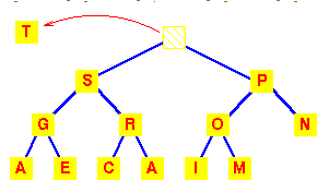
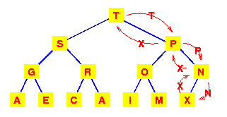
Let's start with this heap. A deletion will remove the T
at the root.
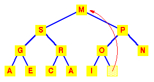
To work out how we're going to maintain the heap property, use the fact that a complete tree is filled from the left. So that the position which must become empty is the one occupied by the M. Put it in the vacant root position.
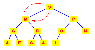
This has violated the condition that the root must be greater than each of its children. So interchange the M with the larger of its children.
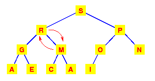
The left subtree has now lost the heap property. So again interchange the M with the larger of its children.
This tree is now a heap again, so we're finished. We need to make at most h interchanges of a root of a subtree with one of its children to fully restore the heap property. Thus deletion from a heap is O(h) or O(logn).

Addition to a heap

To add an item to a heap, we follow the reverse procedure. Place it in the next leaf position and move it up.
Again, we require O(h) or O(logn) exchanges.

Storage of complete trees

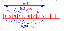
The properties of a complete tree lead to a very efficient storage mechanism using n sequential locations in an array.
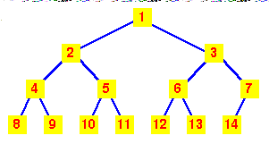
If we number the nodes from 1 at the root and place:
  • the left child of node k at position 2k
  • the right child of node k at position 2k+1
Then the 'fill from the left' nature of the complete tree ensures that the heap can be stored in consecutive locations in an array.
Viewed as an array, we can see that the nth node is always in index position n.
The code for extracting the highest priority item from a heap is, naturally, recursive. Once we've extracted the root (highest priority) item and swapped the last item into its place, we simply call MoveDown recursively until we get to the bottom of the tree.
Click here to load heap_delete.c
Note the macros LEFT and RIGHT which simply encode the relation between the index of a node and its left and right children. Similarly the EMPTY macro encodes the rule for determining whether a sub-tree is empty or not.
Inserting into a heap follows a similar strategy, except that we use a MoveUp function to move the newly added item to its correct place. (For the MoveUp function, a further macro which defines the PARENT of a node would normally be added.)
Heaps provide us with a method of sorting, known as heapsort. However, we will examine and analyse the simplest method of sorting first.

Animation

In the animation, note that both the array representation (used in the implementation of the algorithm) and the (logical) tree representation are shown. This is to demonstrate how the tree is restructured to make a heap again after every insertion or deletion.


Key terms

Complete Tree
A balanced tree in which the distance from the root to any leaf is either h or h-1. 
7.2 Heap Sort We noted earlier, when discussing heaps, that, as well as their use in priority queues, they provide a means of sorting:
  1. construct a heap,
  2. add each item to it (maintaining the heap property!),
  3. when all items have been added, remove them one by one (restoring the heap property as each one is removed).
Addition and deletion are both O(logn) operations. We need to perform n additions and deletions, leading to an O(nlogn) algorithm. We will look at another efficient sorting algorithm, Quicksort, and then compare it with Heap sort.

Animation

The following animation uses a slight modification of the above approach to sort directly using a heap. You will note that it places all the items into the array first, then takes items at the bottom of the heap and restores the heap property, rather than restoring the heap property as each item is entered as the algorithm above suggests. (This approach is described more fully in Cormen et al.) Note that the animation shows the data
  • stored in an array (as it is in the implementation of the algorithm) and also
  • in the tree form - so that the heap structure can be clearly seen.
Both representations are, of course, equivalent. 

Sorting

7 Sorting
Sorting is one of the most important operations performed by computers. In the days of magnetic tape storage before modern data-bases, it was almost certainly the most common operation performed by computers as most "database" updating was done by sorting transactions and merging them with a master file. It's still important for presentation of data extracted from databases: most people prefer to get reports sorted into some relevant order before wading through pages of data!

7.1 Bubble, Selection, Insertion Sorts

There are a large number of variations of one basic strategy for sorting. It's the same strategy that you use for sorting your bridge hand. You pick up a card, start at the beginning of your hand and find the place to insert the new card, insert it and move all the others up one place.
/* Insertion sort for integers */

void insertion( int a[], int n ) {
/* Pre-condition: a contains n items to be sorted */
    int i, j, v;
    /* Initially, the first item is considered 'sorted' */
    /* i divides a into a sorted region, x<i, and an
       unsorted one, x >= i */
    for(i=1;i<n;i++) {
        /* Select the item at the beginning of the
           as yet unsorted section */
        v = a[i];
        /* Work backwards through the array, finding where v 
           should go */
        j = i;
        /* If this element is greater than v,
              move it up one */
        while ( a[j-1] > v ) {
          a[j] = a[j-1]; j = j-1;
          if ( j <= 0 ) break;
          }
        /* Stopped when a[j-1] <= v, so put v at position j */
        a[j] = v;
        }
    }    


Bubble Sort

Another variant of this procedure, called bubble sort, is commonly taught:
/* Bubble sort for integers */
#define SWAP(a,b)   { int t; t=a; a=b; b=t; }

void bubble( int a[], int n )
/* Pre-condition: a contains n items to be sorted */
    {
    int i, j;
    /* Make n passes through the array */
    for(i=0;i<n;i++)
        {
        /* From the first element to the end
           of the unsorted section */
        for(j=1;j<(n-i);j++)
           {
           /* If adjacent items are out of order, swap them */
           if( a[j-1]>a[j] ) SWAP(a[j-1],a[j]);
           }
        }
    }    

Analysis

Each of these algorithms requires n-1 passes: each pass places one item in its correct place. (The nth is then in the correct place also.) The ith pass makes either ior n - i comparisons and moves. So:
or O(n2) - but we already know we can use heaps to get an O(n logn) algorithm. Thus these algorithms are only suitable for small problems where their simple code makes them faster than the more complex code of the O(n logn) algorithm. As a rule of thumb, expect to find an O(n logn) algorithm faster for n>10 - but the exact value depends very much on individual machines!. They can be used to squeeze a little bit more performance out of fast sort algorithms -

Key terms

Bubble, Insertion, Selection Sorts
Simple sorting algorithms with O(n2) complexity - suitable for sorting small numbers of items only.

Binary Sort

7.4 Bin Sort
Assume that in the bin sort
  1. the keys of the items that we wish to sort lie in a small fixed range and
  2. that there is only one item with each value of the key.
Then we can sort with the following procedure:
  1. Set up an array of "bins" - one for each value of the key - in order,
  2. Examine each item and use the value of the key to place it in the appropriate bin.
Now our collection is sorted and it only took n operations, so this is an O(n) operation. However, note that it will only work under very restricted conditions.

Constraints on bin sort

To understand these restrictions, let's be a little more precise about the specification of the problem and assume that there are m values of the key. To recover our sorted collection, we need to examine each bin. This adds a third step to the algorithm above,
  1. Examine each bin to see whether there's an item in it.
which requires m operations. So the algorithm's time becomes:
T(n) = c1n + c2m
and it is strictly O(n + m). Now if m <= n, this is clearly O(n). However if m >> n, then it is O(m). For example, if we wish to sort 104 32-bit integers, then m = 232 and we need 232 operations (and a rather large memory!).
For n = 104:

nlogn ~ 104 x 13 ~ 213 x 24 ~ 217
So quicksort or heapsort would clearly be preferred. An implementation of bin sort might look like:
#define EMPTY -1 /* Some convenient flag */
void bin_sort( int *a, int *bin, int n ) {
    int i;
    /* Pre-condition: for 0<=i<n : 0 <= a[i] < M */
    /* Mark all the bins empty */
    for(i=0;i<M;i++) bin[i] = EMPTY;
    for(i=0;i<n;i++)
        bin[ a[i] ] = a[i];
    }

main() {
    int a[N], bin[M];    /* for all i: 0 <= a[i] < M */
    .... /* Place data in a */
    bin_sort( a, bin, N );

If there are duplicates, then each bin can be replaced by a linked list. The third step then becomes:
  1. Link all the lists into one list.
We can add an item to a linked list in O(1) time. There are n items requiring O(n) time. Linking a list to another list simply involves making the tail of one list point to the other, so it is O(1). Linking m such lists obviously takes O(m) time, so the algorithm is still O(n+m). In contrast to the other sorts, which sort in place and don't require additional memory, bin sort requires additional memory for the bins and is a good example of trading space for performance.
Although memory tends to be cheap in modern processors -
so that we would normally use memory rather profligately to obtain performance,
memory consumes power
and in some circumstances, eg computers in space craft,
power might be a higher constraint than performance.
Having highlighted this constraint, there is a version of bin sort which can sort in place:
#define EMPTY -1 /* Some convenient flag */
void bin_sort( int *a, int n ) {
    int i;
    /* Pre-condition: for 0<=i<n : 0 <= a[i] < n */
    for(i=0;i<n;i++)
 if ( a[i] != i )
            SWAP( a[i], a[a[i]] );
    }
However, this assumes that there are n distinct keys in the range 0 .. n-1. In addition to this restriction, the SWAP operation is relatively expensive, so that this version trades space for time. The bin sorting strategy may appear rather limited, but it can be generalised into a strategy known as Radix sorting.

Radix

7 Radix Sorting
The bin sorting approach can be generalised in a technique that is known as radix sorting.

An example

Assume that we have n integers in the range (0,n2) to be sorted. (For a bin sort, m = n2, and we would have an O(n+m) = O(n2) algorithm.) Sort them in two phases:
  1. Using n bins, place ai into bin ai mod n,
  2. Repeat the process using n bins, placing ai into bin floor(ai/n), being careful to append to the end of each bin.
This results in a sorted list. As an example, consider the list of integers:
36 9 0 25 1 49 64 16 81 4
n is 10 and the numbers all lie in (0,99). After the first phase, we will have:
Bin01 23 45 67 89
Content 0 1
81
-- 64
4
25 36
16
- - 9
49
Note that in this phase, we placed each item in a bin indexed by the least significant decimal digit.
Repeating the process, will produce:

Bin01 23 45 67 89
Content 0
1
4
9
16 25 36 49 - 64 - 81 -
In this second phase, we used the leading decimal digit to allocate items to bins, being careful to add each item to the end of the bin.
We can apply this process to numbers of any size expressed to any suitable base or radix.

7.5.1 Generalised Radix Sorting

We can further observe that it's not necessary to use the same radix in each phase, suppose that the sorting key is a sequence of fields, each with bounded ranges, eg the key is a date using the structure:
typedef struct t_date {
    int day;
    int month;
    int year; 
} date;
If the ranges for day and month are limited in the obvious way, and the range for year is suitably constrained, eg 1900 < year <= 2000, then we can apply the same procedure except that we'll employ a different number of bins in each phase. In all cases, we'll sort first using the least significant "digit" (where "digit" here means a field with a limited range), then using the next significant "digit", placing each item after all the items already in the bin, and so on. Assume that the key of the item to be sorted has k fields, fi|i=0..k-1, and that each fi has si discrete values, then a generalised radix sort procedure can be written:
radixsort( A, n ) {
    for(i=0;i<k;i++) {
        for(j=0;j<si;j++) bin[j] = EMPTY;
O(si)
        for(j=0;j<n;j++) {
            move Ai 
            to the end of bin[Ai->fi]
            }
O(n)
        for(j=0;j<si;j++) 
            concatenate bin[j] onto the end of A;
        }
}
O(si)
Total
Now if, for example, the keys are integers in (0,bk-1), for some constant k, then the keys can be viewed as k-digit base-b integers.
Thus, si = b for all i and the time complexity becomes O(n+kb) or O(n). This result depends on k being constant.
If k is allowed to increase with n, then we have a different picture. For example, it takes log2n binary digits to represent an integer <n. If the key length were allowed to increase with n, so that k = logn, then we would have:
.
Another way of looking at this is to note that if the range of the key is restricted to (0,bk-1), then we will be able to use the radixsort approach effectively if we allow duplicate keys when n>bk. However, if we need to have unique keys, then k must increase to at least logbn. Thus, as n increases, we need to have logn phases, each taking O(n) time, and the radix sort is the same as quick sort!

Sample code

This sample code sorts arrays of integers on various radices: the number of bits used for each radix can be set with the call to SetRadices. The Bins class is used in each phase to collect the items as they are sorted. ConsBins is called to set up a set of bins: each bin must be large enough to accommodate the whole array, so RadixSort can be very expensive in its memory usage!

Quickk Sort

Quick Sort
  1. Features
    • Similar to mergesort - divide-and-conquer recursive algorithm
    • One of the fastest sorting algorithms
    • Average running time O(NlogN)
    • Worst-case running time O(N2)

  2. Basic idea
    1. Pick one element in the array, which will be the pivot.
    2. Make one pass through the array, called a partition step, re-arranging the entries so that:
        • the pivot is in its proper place.
        • entries smaller than the pivot are to the left of the pivot.
        • entries larger than the pivot are to its right.
    3. Recursively apply quicksort to the part of the array that is to the left of the pivot,
      and to the right part of the array.
    Here we don't have the merge step, at the end all the elements are in the proper order.
  3. Algorithm
  4. STEP 1. Choosing the pivot
    Choosing the pivot is an essential step.
    Depending on the pivot the algorithm may run very fast, or in quadric time.:
      1. Some fixed element: e.g. the first, the last, the one in the middle
      2. This is a bad choice - the pivot may turn to be the smallest or the largest element,
        then one of the partitions will be empty.
      3. Randomly chosen (by random generator ) - still a bad choice.
      4. The median of the array (if the array has N numbers, the median is the [N/2] largest number. This is difficult to compute - increases the complexity.
      5. The median-of-three choice: take the first, the last and the middle element.
        Choose the median of these three elements.
    Example:
    8, 3, 25, 6, 10, 17, 1, 2, 18, 5
    The first element is 8, the middle - 10, the last - 5.
    The three elements are sorted: [5, 8, 10] and the middle element is 8. This is the median.
    STEP 2. Partitioning
    Partitioning is illustrated on the above example.
    After finding the pivot the array will look like this:
    5, 3, 25, 6, 8, 17, 1, 2, 18, 10 1. The first action is to get the pivot out of the way - swap it with the next to the last element
    5, 3, 25, 6, 18, 17, 1, 2, 8, 10
    2. We want larger elements to go to the right and smaller elements to go to the left.
    Two "fingers" are used to scan the elements from left to right and from right to left:
    
    [5, 3, 25, 6, 18, 17, 1, 2, 8, 10]
       ^                     ^
       i                     j
    
    Note: we know that the first element is smaller than the pivot, so the first element to be processed is the element to the right. The last two elements are the pivot and an element greater than the pivot, so they are not processed.
    • While i is to the left of j, we move i right, skipping all the elements
      less than the pivot. If an element is found greater then the pivot, i stops
    • While j is to the right of i, we move j left, skipping all the elements
      greater than the pivot. If an element is found less then the pivot, j stops
    • When both i and j have stopped, the elements are swapped.
    • When i and j have crossed, no swap is performed, scanning stops,
      and the element pointed to by i is swapped with the pivot .
    In the example the first swapping will be between 25 and 2, the second between 18 and 1.
    3. Restore the pivot.
    After restoring the pivot we obtain the following partitioning into three groups:
    [5, 3, 2, 6, 1] [ 8 ] [18, 25, 17, 10]
    STEP 3. Recursively quicksort the left and the right parts
  5. Code
  6. Here is the code, that implements the partitioning.
    left points to the first element in the array currently processed, right points to the last element.
    
    if( left + 10 <= right)
        {
     int i = left, j = right - 1;
     for ( ; ; )
       {
         while (a[++i] < pivot  ) {}   // move the left finger
         while (pivot  < a[--j] ) {}   // move the right finger
    
         if (i < j) swap (a[i],a[j]);  // swap 
                else  break;    // break if fingers have crossed
              }
           swap (a[I], a[right-1]);    // restore the pivot
           quicksort ( a, left, i-1);   // call quicksort for the left part
           quicksort (a, i+1, right);   // call quicksort for the left part
         }
    else  insertionsort (a, left, right);
    
    
    If the elements are less than 10, quicksort is not very efficient.
    Instead insertion sort is used at the last phase of sorting.
    Click here to see the above example worked out in details
    Animation:
    http://math.hws.edu/TMCM/java/xSortLab/
    In the animation, the leftmost element is chosen as a pivot.
  7. Implementation notes
  8. Compare the two versions:
    
    A.
     while (a[++i] < pivot) {}
     while (pivot < a[--j]) {}
    
     if (i < j) swap (a[i], a[j]);
     else break;
    
    B.
    
     while (a[i] < pivot) {i++;}
     while (pivot < a[j] ) {j--;}
    
     if (i < j) swap (a[i], a[j]);
     else break;
    
    If we have an array of equal elements, the second code will never increment i or decrement j,
    and will do infinite swaps. i and j will never cross.
  9. Complexity of Quicksort
  10. Worst-case: O(N2)

    This happens when the pivot is the smallest (or the largest) element.
    Then one of the partitions is empty, and we repeat recursively the procedure for N-1 elements.
    Best-case O(NlogN) The best case is when the pivot is the median of the array,
    and then the left and the right part will have same size.
    There are logN partitions, and to obtain each partitions we do N comparisons
    (and not more than N/2 swaps). Hence the complexity is O(NlogN)
    Average-case - O(NlogN)
    Analysis
    T(N) = T(i) + T(N - i -1) + cN
    The time to sort the file is equal to
    • the time to sort the left partition with i elements, plus
    • the time to sort the right partition with N-i-1 elements, plus
    • the time to build the partitions
    6. 1. Worst case analysis
    The pivot is the smallest element
    T(N) = T(N-1) + cN, N > 1 Telescoping:
    T(N-1) = T(N-2) + c(N-1)
    T(N-2) = T(N-3) + c(N-2)
    T(N-3) = T(N-4) + c(N-3)
    T(2) = T(1) + c.2
    Add all equations:
    T(N) + T(N-1) + T(N-2) + … + T(2) =
    = T(N-1) + T(N-2) + … + T(2) + T(1) + c(N) + c(N-1) + c(N-2) + … + c.2
    T(N) = T(1) + c(2 + 3 + … + N)
    T(N) = 1 + c(N(N+1)/2 -1)
    Therefore T(N) = O(N2) 6. 2. Best-case analysis:
    The pivot is in the middle
    T(N) = 2T(N/2) + cN
    Divide by N:
    T(N) / N = T(N/2) / (N/2) + c
    Telescoping:
    T(N/2) / (N/2) = T(N/4) / (N/4) + c
    T(N/4) / (N/4) = T(N/8) / (N/8) + c
    ……
    T(2) / 2 = T(1) / (1) + c
    Add all equations:
    T(N) / N + T(N/2) / (N/2) + T(N/4) / (N/4) + …. + T(2) / 2 =
    = (N/2) / (N/2) + T(N/4) / (N/4) + … + T(1) / (1) + c.logN
    After crossing the equal terms:
    T(N)/N = T(1) + cLogN = 1 + cLogN
    T(N) = N + NcLogN
    Therefore T(N) = O(NlogN)
    6. 3. Average case analysis
    Similar computations, resulting in T(N) = O(NlogN)
    The average value of T(i) is 1/N times the sum of T(0) through T(N-1)
    1/N S T(j), j = 0 thru N-1
    T(N) = 2/N (S T(j)) + cN
    Multiply by N
    NT(N) = 2(S T(j)) + cN*N
    To remove the summation, we rewrite the equation for N-1:
    (N-1)T(N-1) = 2(S T(j)) + c(N-1)2, j = 0 thru N-2
    and subtract:
    NT(N) - (N-1)T(N-1) = 2T(N-1) + 2cN -c
    Prepare for telescoping. Rearrange terms, drop the insignificant c:
    NT(N) = (N+1)T(N-1) + 2cN
    Divide by N(N+1):
    T(N)/(N+1) = T(N-1)/N + 2c/(N+1)
    Telescope:
    T(N)/(N+1) = T(N-1)/N + 2c/(N+1)
    T(N-1)/(N) = T(N-2)/(N-1)+ 2c/(N)
    T(N-2)/(N-1) = T(N-3)/(N-2) + 2c/(N-1)
    ….
    T(2)/3 = T(1)/2 + 2c /3
    Add the equations and cross equal terms:
    T(N)/(N+1) = T(1)/2 +2c S (1/j), j = 3 to N+1
    T(N) = (N+1)(1/2 + 2c S(1/j))
    The sum S (1/j), j =3 to N-1, is about LogN
    Thus T(N) = O(NlogN)
  11. Conclusions
  12. Advantages:
    • One of the fastest algorithms on average.
    • Does not need additional memory (the sorting takes place in the array - this is called in-place processing). Compare with mergesort: mergesort needs additional memory for merging.
    Disadvantages: The worst-case complexity is O(N2)
    Applications:
    Commercial applications use Quicksort - generally it runs fast, no additional memory,
    this compensates for the rare occasions when it runs with O(N2)
    Never use in applications which require guaranteed response time:

    • Life-critical (medical monitoring, life support in aircraft and space craft)
    • Mission-critical (monitoring and control in industrial and research plants
      handling dangerous materials, control for aircraft, defense, etc)
    unless you assume the worst-case response time. Comparison with heapsort:
    • both algorithms have O(NlogN) complexity
    • quicksort runs faster, (does not support a heap tree)
    • the speed of quick sort is not guaranteed
    Comparison with mergesort:
    • mergesort guarantees O(NlogN) time, however it requires additional memory with size N.
    • quicksort does not require additional memory, however the speed is not quaranteed
    • usually mergesort is not used for main memory sorting, only for external memory sorting.
    So far, our best sorting algorithm has O(nlog n) performance: can we do any better?
    In general, the answer is no.

Learning Goals
  • Be able to explain how quicksort works and what its complexity is (worst-case, best-case, average case).
  • Be able to compare quicksort with heapsort and mergesort.
  • Be able to explain the advantages and disadvantages of quicksort,
    and its applications.

Exam-like questions

  1. Briefly describe the basic idea of quicksort.
  2. What is the complexity of quicksort?
  3. Analyze the worst-case complexity solving the recurrence relation.
  4. Analyze the best-case complexity solving the recurrence relation.
  5. Compare quicksort with mergesort and heapsort.
  6. What are the advantages and disadvantages of quicksort?
  7. Which applications are not suitable for quicksort and why?