Tuesday 13 October 2015

HTTP Format

HTTP Types and Its Message Format

Moving on with our discussion on Hyper Text Transfer Protocol (HTTP). If you have forget something about HTTP, then you can go to this link and revise it, and then start with this post. HTTP Revise..

In this post, I am going to tell you about the types of HTTP connections and HTTP message format.


First we will start with the HTTP connection types. There are basically two types of HTTP connections: Persistent and Non-Persistent. Lets have a look at each one of them.

When you or any host communicate with the server, there is a long series of request-response messages, that is being exchanged between you and the server. Therefore, depending on the type of application, the Application developer has to make a decision, that should all the request-response messages should be sent over a single TCP connection or they should be sent under individual TCP connection for every pair of request-response message.

If all the request-response message pair are sent over different TCP connection, it is known as Non-Persistent Connections and if there is only one TCP connection for a series of messages, it is known as Persistent Connection.

Hyper Text Transfer Protocol (HTTP) with   non-persistent connection :

Let me start by giving you an example that will make you understand about HTTP non-persistent connection. The transfer of a Web Page from server to client under non-persistent connection is as follows:
Let us suppose that a web page consists of a base HTML file and 20 PNG images, all these 21 files reside on the same server. Say, the address or the URL of the base HTML file is http://www.com2networks.blogspot.com/department/images.html.
Now the process starts.
1. The HTTP client process initiates a TCP connection to the server www.com2networks.blogspot.com on port number 80, the default port number for HTTP. There will be a socket at the client and a socket at the server associated with the TCP connection
2. The HTTP client sends an HTTP request message to the server via its socket. The request message includes the path name /department/images.html.
3. The HTTP server process receives the request message via its socket, retrieves the object /department/images.html from its storage, encapsulates or embed the object in an HTTP response message, and sends the response message to the client via its socket.
4. The HTTP server process tells TCP to close the TCP connection.
5. The HTTP client receives the response message. The TCP connection terminates. The message indicates that the encapsulated object is an HTML file. The client extracts the file from the response message, examines the HTML file and finds references to the 20 PNG objects.
6. Now to get those 20 PNG images, the first four steps are again repeated.
The steps above explains you the use of non-persistent connections, where each TCP connection is closed after the server sends the object—the connection does not persist or remains for other objects. Each TCP connection transports only one request message and one response message. Therefore in this case, when a user requests the Web page, 21 TCP connections must be generated.
Lets now see into the depth of non-persistent connection and calculate the time taken from requesting a web page and till the entire file is received.
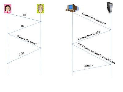
Here I will describe you the time taken by a small packet to travel from client to server and back to client. This is known as Round-Trip Time (RTT). The RTT includes the packet propagation delay, queuing delay at the router and switches and the the processing delay.
What happens when you click on a link or a hyperlink , the client or your browser initiates a TCP connection with the server. This connection involves 3 steps that are often called as "3-way handshake". This handshake includes, (a) The client sends a TCP segment to the server, (b) The server acknowledges and responds with a  TCP segment, and finally (c) The client acknowledges back to the server.
The 1st two parts (a) and (b) takes 1 RTT. After completing the 1st two steps , the client sends a request message along with the 3rd part of handshake i.e. acknowledgement to server. After receiving the request message and acknowledgement , the server respond by sending the HTML file into the TCP connection. This HTTP request-response takes 1 RTT. So approximately, we can say that, Total response time taken is 2 RTT's plus the transmission time taken by the server. Now as usual, I will clear  it by drawing a figure for you.
round trip time, rtt, propagation delay, queuing delay, file transmission, transmission delay,
         Figure: TIME TAKEN IN TRANSMISSION OF A HTML FILE

Hyper Text Transfer Protocol (HTTP) with persistent connection :

As we can clearly see that , non-persistent connections have certain disadvantages. For every requesting object, you have to set-up a new TCP connection that is a huge overhead for a server that is serving millions of requests. And also, it will take 2 RTT for every requested object.
To overcome theses issues, HTTP is used with persistent connections. In persistent connection, the server doesn't close the connection after sending a response. More than one request and response can be sent between the same client and the same server over the same TCP connection. The example we have taken above of an HTML file and 20 PNG images. So these 21 objects can be sent over a single persistent connection.The request for different objects are made simultaneously without waiting for the replies to the pending requests. This phenomenon is often called as pipelining.  When the server receives back-to-back requests, it sends the objects back-to-back. The server closes the connection , when the connection remains useless or idle for a particular time period.
  • The default mode of HTTP uses persistent connections. However an application developer can modify it to non-persistent according to his need.
Now lets move on and have a look at the types of HTTP message formats. As you already know, there are two types of HTTP message. One is Request message and the other is the Response message.

HTTP REQUEST MESSAGE

GET    /department/images.html    HTTP/1.1
Host : www.com2networks.blogspot.com
Connection : close
User-agent : Chrome/7.0
Language : Fr


Have a look at this message and try to understand it. You can see that the message is written in ASCII text, so that an ordinary human being can read it. As this request message contains 5 lines. Similarly a request message can have more lines and as few as 1 line also.

In this example, the 1st line of the message is said to be the request line and the further are called the header lines.

Request line: It has 3 fields: (a) Method field, (b) URL field and (c) HTTP version field.
There are various methods that can be there in a method field such as GET, POST, PUT, HEAD, DELETE.

GET:    The GET method is used for general web page request.
POST:  The POST method is used to ad parameters to the server.

The URL field contains the address of the requested object. As here, it is /department/images.html.

Version field: Version of the HTTP that browser implements, here it is version HTTP/1.1.


Now the header fields.

1st header field contains the host i.e. www.com2networks.blogspot.com, tells the name of the host on which the objects reside.
2nd header field Connection:close , browser tells the server that it doesn't want to bother with persistent connection. It wants server to close the connection after sending the requested object.

3rd header field User-agent : Chrome/7.0, a chrome browser. This field is useful in the cases where the server has different copies of the files for different version of user agent.

4th header field Language: Fr. It tells the server in which language , the desired copy of the requested file is wanted. Here it is French. If the server has the requested copy, it will send that, but if it doesn't , then it will response with the default version.


Now let me give you a  general format of HTTP request message.
HTTP request message, header filed, request line, department, connection

HTTP RESPONSE MESSAGE

HTTP/1.1    200     OK

Connection: close

Date: Fri, 06 Sept 2013 11:45:07 (GMT +05:30)

Server: Apache/2.2.3 

Last-Modified: Sun, 01 Sept 2013 15:11:03 (GMT+05:30)

Content-Length: 4951

Content-Type: text/html

(data data data data data ...)

A response message could have more number of entries also. But we will discuss this basic message with 8 entries.

Have a look at this message and try to understand this. It basically has 3 sections. 1. An initial status line 2. Header lines 3. Entity body.

1. Status Line: It has 3 fields. (a) The protocol version. (b) A status code. (c) Status message

In the given message, the server is using HTTP/1.1 version and the code is 200 , that means everything is OK and executed properly (The server has found the object and sending it).

  • Some common Status Code that you will generally get as response from the server, while   requesting for a Web page are:


                         (i)  200 OK : It means , The Request succeed and the requested information has been sent.

                        (ii) 301 Moved permanently : It indicate that the requested URL has been permanently                  moved to a new address. This new URL will be indicated in the Location, header of the response message.

                        (iii) 400 Bad Request : When server doesn't understand the request, it shows this code.

                         (iv) 404 Not Found : The requested information doesn't exist on this server.


2. Now the header fields.

1st header field Connection : close, The server wants to inform the client that it is going to close the connection after sending the object.

2nd header field DATE : It indicated the time and the date when the HTTP response was sent by the server.

3rd header field Server : The name of the server used to generate the response message.

4th header field Last-Modified : Its the time and the date when the object was last created or modified.

5th header field Content-Length : It tells about the number of bytes in the response message that are being sent.

6th header field Content Type : It tells that the object in the entity body is a HTML text.


3. Entity body that is being denoted by data data data data....... is the meat of the message . It contains the requested object.


Let me give you a general format of HTTP response message.


http response message, header fields, connection, status line, header lines, entity body
 I am done with the HTTP protocol. In the coming posts , we will discuss about the other Application Layer Protocols such as FTP, SMTP, DNS

Network

COMPUTER NETWORKING

A network is a collection or a group of people interacting and sharing information with each other, So in the same way , a Computer network is a group of computer that interacts and share information with each other , connected by some communication links such as wires, cable or wirelessly. It is all about transmitting message from sender to receiver and vice-versa. A computer network can be wired and wireless.
There are various mediums to make a wired network. These are:
Mediums to form a wireless network are:
There are various kinds of Networks. These are:
i) Personal Area Network (PAN):

A Personal Area Network (PAN) is a computer network that is used to transfer messages between a computer and other technological devices that belongs to one person only.  Example of such devices are a laptop or desktop, fax machine, Personal Digital Assistance (PDA) or Palmtop computer, scanner , printer etc. The range of a PAN is around 10 metres. 
ii) Local Area Network (LAN):
A  Local Area Network (LAN) is a computer network that is set-up within a home, college, institution, college and there nearby buildings. The connected computers are called nodes of this computer network. The wired LAN can be formed using an Ethernet cable. The range of a LAN is about 100-150 metres.
iii) Metropolitan Area Network (MAN):
A Metropolitan Area Network (MAN) is a computer network that is set-up for a whole city or a very large area. MAN can cover a region of almost 30-40 kilometres. 
iv) Wide Area Network(WAN):
A Wide Area Network(WAN) is a computer network that is set-up along a big area such as a WAN covering two or more cities, a country, a continent. The best example of WAN is Internet.
Now after defining the network analogies, we should move on to the Internet and should look into some aspects of Internet.

When we talk about internet , we all have some very basic questions about internet. So here are the answers to your questions..

Ques 1. What is an Internet ?

Internet is a collection of computers i.e. it is a network of networks in which million of computer are connected and interacting with each other. People are connected to the Internet from all over the world through different devices such as desktops, laptops, smartphones, tablets etc. These all devices in networking are called as hosts or end users or nodes. According to a survey conducted in 2011, more than 2 billion hosts were connected to Internet.
Ques 2. How do different end users communicate with each other over computer networks?
Now directly before answering your question, I want to ask something from you. Suppose when you want to ask time from a stranger. How do you do it. You first say "Hi" (Greet message) to initiate the communication, then he will reply you with "Hi"( a message that you will take as an indication, that the receiver is willing to communicate and you can proceed to ask time). Or the other replies could be "Don't bother me" or "I don't understand your language", indicates the unwillingness to communicate. So you would not ask time.
These were the human protocols, that before initiating you should say a "Hi" or "Hello"(or at-least your manners), then the reply from the receiver , that will indicate you, whether you should proceed with asking time or not.
Same is the procedure in computer networks except that here the messages are exchanged between systems and machines and their hardware and software. The requesting node will send a requesting message to the receiver, then receiver will send a reply message, whether he is ready to communicate or not, and the communication will move on. This is often called as a 3-way handshake, that we will discuss in later articles. The figure below will make you understand this more clearly.

This whole procedure is governed by certain set of rules , that are called as protocols.

Ques 3. What are the different ways of sending data ?
The message or the data is called as packet in computer networks. So sending of packets can be done be done in 2 ways. Circuit switching and Packet Switching.

Ques 4. What are protocols?

A protocol defines the type, method and the order of the messages exchanged between the sender and the receiver node, and the actions to be taken after the transmission or the receipt of the message.
Ques 5. What are the problems that occur after setting up a network?

There are certain problems that we have to take into account to have proper transmission of message from sender to receiver. There can be Noise, various delays while transmitting, interference from outside etc.
Ques 6. How many protocol Layering are there?
There are basically two models of protocol layering .One is said to be Open Systems Interconnection(OSI ) layer model and the other is TCP/IP model.
In OSI model, there are 7 layers while in TCP/IP model, there are 5 layers of protocols.
Ques 7. Is there any threat to our networks to our hosts?

Yes, there are lots of threats engaged when you are connected to an Internet. There are two types of attacks, Active and Passive attacks. These attacks can include Denial of Service attacks, virus attacks, infrastructure attacks etc.


OSI App

The Top Most Layer : Application Layer

The Application Layer is the 1st layer in the TCP/IP stack according to Top-Down Approach. The Computer Applications are the main reason behind the existence of the computer networks. If there wouldn't have been any Application, then there was no need of any transport or networking protocol, that support these applications. After the Internet came into existence , number of useful , entertaining and applications have been developed and still the procedure is on.

Beginning from the text based applications, such as text mails, file transfers, further e-commerce websites and the world wide web. Now from the last couple of years , number of voice and video conferencing applications are developed. Such as , For android, there are two voice chat applications , We-chat and LINE. Video applications like Skype, Gmail video conferencing etc. are being developed.

There has been no slowing down of dashing and super applications to be developed. And I hope, you can also create a killer application for your future generation.

To begin with the further discussion , I want to tell you one more thing. Before developing an application, you should have a basic understanding that how the programs on the different hosts communicate with each other. In computer networks, its not the programs but the the processes that communicate with each other. A process can be termed as the subset of a program, that is running within a system. Processes on two different hosts communicate with each other by exchanging messages across the computer network. A sending process creates and sends messages into the network a receiving process receives these messages and responds by sending messages back. So you remember this, throughout your network study, that processes communicate. Two processes on same hosts communicate via Interprocess Communication. So now you are ready and we should move on.


Aspects of Network Applications:

Now you must also be thinking of developing a new application. Either the application is good for your country or is a video game for children. Whatever may be the reason or motivation behind your development. But there are many principles that you have to learn, in order to convert your idea into a real world application.
You have to develop an application that should run on different hosts and can interact with each other over the network. For Example: In Web applications, there are two processes that interact with each other. A Web Browser process running on the Client or user's side(can be a desktop, laptop or ipad) and a Web Browser process running on the on the Server side. 
Therefore, while developing a new application , you should always take into consideration, that it must be capable of running on multiple different hosts or end systems.

Architecture:

There are basically two Application architecture that you can use for communication between hosts. These are: Client-Server Architecture and Peer-to-Peer Architecture (P2P).

                  1. Client-Server Architecture


There is a always a server, which responds to requests from other hosts, called clients. For Example: The Web Application. In this this is a Web Sever that is always ON, that responds to request from browsers running on client systems. 
 Briefly we can say that, a process that initiates the communication is Client. The process that waits to be contacted is a Server.
introduction to application layer, server, client, client-server architecture, peer-2-peer architecture

Characteristics of Client-Server Architecture


1. Two clients never communicate directly with each other. For Example: Two browsers never communicate directly.
2. The Server has a well known address that is known as IP address in networking. The IP address of Server is always fixed. Because of this feature, the client can any-time contact the server by sending a packet to its IP address.
Some Examples of Client-Server Architecture Applications are E-mail, FTP, Telnet etc.


Problems with Client-Server Architecture


Many times, a single server is incapable of responding to all he requests of the clients. For Example: A Google server gets millions of requests every second, So its impossible for it to respond from a single system. To overcome this problem, the Data Center, combination of large number of hosts, is formed. Data Center is a virtual Server that is a combination of 1000's of servers that works as a single host. That's why they are called virtual server. Companies such as Yahoo, Google, Facebook have one or more data centers.


                  2. Peer-to-Peer Architecture (P2P)

In P2P Architecture, the end systems directly communicate with each other known as peers. Much of the Peers are not owned by the Service provide but, infact owned by the users. These peers can be at houses, offices or universities. Since the users communicate without passing by a dedicated sever, this called as P2P sharing. Examples of such Applications is Bit Torrent, that relies on the peers. Another example is Skype.
peer-2-peer architecture, computer networks, communication medium, direct interaction

Characteristics of P2P Architecture


It is self-scalable. As the users are directly communicating , so they don't have to depend on the server for space scalability and bandwidth. This is the most promising feature of P2P Architecture.

Problems with P2P Architecture


Security is the major drawback of this architecture. As there is no dedicated server for communications.

There is also a 3rd type of Architecture that is a combination of both Client-Server Architecture and P2P  Architecture. This is known as Hybrid Architecture. It is used in the cases, where you need the address of the two communicating hosts but after that, both the host will communicate each other. A very good example of this is Instant Messaging.


What you do in Instant Messaging is that you register yourself with a server. Like you register yourself with a website named Facebook. But after registering, you directly chat with your your friends and relatives. And they can reply you back. In such applications, the use of Hybrid Architecture is essential.******


  • Interaction Between Processes and Computer Networks

There are always two processes that are communicating with each other. Every process that wants to send message to other process has to send through the underlying network and underlying networking layers. A process sends and receive a message from the network through a device or a software, called as socket.


Let me give you an example , so you clearly understand what a socket is. 

Suppose you want to send a message to your friend ( say James). Here you are the process. Now what will you do. You will write a message and put into an envelope and will go and open the door, so that you should give this envelope to the postman who can deliver your envelope to your friend. Here your house door is the socket and the postman and the post-office are the underlying network and the networking layers. In the same way, the network will deliver the envelope to your friend , through his house door. There your friend is process and the door is socket.

Let me now try to explain it by drawing a figure.
process communication, socket, process, application developer, operating system, friend, destination address

As it is shown in the figure, the two processes communicating over the Internet. The Socket is the Interface between the Application Layer and the Underlying Transport layer, so it is also called as Application Programming Interface (API) . Since Socket is the API software with which the network applications are built. The Application developer has full control over the application side socket. But he doesn't have control over the transport layer side socket. On Transport Layer side socket, he can only control 2 things , that are
1. He can chose the type of protocol to be used, if choice is available and 2. He can set the maximum size of buffer or queue. And after choosing the protocol by the Application Developer, the Application is developed using the services provided by transport layer protocols.


How to Determine the Address of the Processes


If you want to send a parcel to someone, than that parcel should have your as well as the destination Address. In the same way, in computer networks, to send a packet to a host, the address of the destination host should be known. For identification of the receiving process, two things should be known. 1. Address of the host. 2. An identifier that specifies the receiving process in the destination host.
In Computer Networks, Inspite of having alphabetical addresses, hosts have IP address. I will tell you about IP address in detail in the coming posts. Till now, you should only remember that IP address is a 32-bit quantity that is a address of a host.Except the address of the host, the sending process should also know about the receiving process. Because in reality, there are many processes or applications running on a single host. For example, you could be running an email application , a Web application, a FTP application on your system. So to serve this purpose, PORT NUMBER is used. A particular port number is given to every application. For a Web application , port number 80 is assigned, for an email application , port number 25 is there. So these are the two basic things that a sender process should know about the receiver process.
You can found port numbers of different Internet Protocols by visiting this link. IANA


This was all , I had with the Application Layer. Will meet you soon with the Application Layer Protocols.

Delays

DELAYS IN TRANSMISSION

All of us want Internet and its services to be able to move as much data as we want
between two end users or hosts, instantaneously and without any loss of data. Unfortunately, this
is just an imaginary perception that is cannot be done in reality. Infact computer networks necessarily
 introduce delays between hosts and can actually lose packets.

There are various types of delays in networks that occur due to various factors . These factors can be      

  •          Overhead in the communication link.
  •          The slow transmission rate of the link.
  •          Position of the hosts from each other.

 There are various reasons that account to the delays in the transmission of data in the network. So lets start  by looking at the delays and understanding them.

 1. Processing Delay (dproc):

Processing Delay is the time that is taken by the router to access the header of a packet and redirect it to the next path. This time is known as processing delay. Processing also include to check the next destination address of the packet as well as checking for any bit error in the packets, that can occur during transmission of the packet. Processing delay in high speed router is mostly in the order of microseconds. However it can be large, if the router is processing big encryption and decryption algorithms for processing packet header.

After all this processing , the router sends the packet to the queue that precedes the link to the next router( i.e. router B).


 2. Queuing Delay( dqueue):

Queuing Delay is the time that a packet has to wait in the queue before it can be transmitted over the link. Packets are put in the queue when the speed of incoming link to the router is faster than the outgoing link. Queuing delay depends on the number of earlier arrived packets already waiting for getting transmitted. If the queue is empty, then the queuing delay is zero, and if the traffic or the number of incoming packets is high, then the queuing delay is high. Queuing delay is mostly in order from microseconds to milliseconds.

Queuing Delay can be higher if the size of the queue or the buffer is very small.

 3. Transmission Delay( dtrans):

Transmission delay is usually caused by the data rate of the link. It is the time taken to push all the packet bits on to the link. For example : If the date rate of the link is 10 Mbps and your packet size 100 Kbps. Then the transmission Delay = 100 Kbps/10 Mbps = (100*1000)/ (10*1000000) = (1/100)seconds= .01 seconds.

As 1 Mbps = 1000000 bps       &    1 Kbps = 1000 bps.

To generalise this, if our packet is of M bits and link data rate is R bits/sec, then Transmission Delay = M/R seconds.

 4. Propagation Delay( dprop):

Propagation Delay is the time taken by the 1st bit of the packet to reach the receiver router. It can be calculated by dividing the distance between the two routers and the speed of propagation of the link.

For example:

d= distance between the routers
s=speed of propagation (almost equal to speed of light)

As the communication medium we use as copper wire or fibre optics, so in that propagation speed is equal to speed of light=3*(10^8) metres/second.

Propagation Delay = d/s


A delay for a packet at a router is said to be Nodal Delay (dnodal).

So the Nodal Delay is equal to the some of all the Delays for a packet.

                                         dnodal   =  dproc +  dqueue + dtrans+ dprop

Now , you should go through this Diagram, then you will be clear with all the Networking Delays.


Delays in computer networking, processing delay, transmission delay, propagation delay, queuing delay, nodal delay

Switching

Approaches for Moving Data In a Network

Till now we have discussed about the Basics of Computer Networks , Mediums to transfer Data and The Types of Delays in Computer Networks. In this post, I am going to tell you about the approaches or the techniques that are used for moving data in a Computer Network.

There are basically two approaches for moving data from Source host to the Destination Host. These are:
1. Circuit Switching
2. Packet Switching


CIRCUIT SWITCHING

In Circuit Switching, before the two hosts start communicating , the resources along the path are to be reserved, that are needed by the two hosts for their communication. The Resources are reserved for as long as the two hosts communicate.

Now I should give a live example that will make circuit switching clear to you.

Let us suppose that there are 2 restaurants A and B. In restaurant A, there is a need to reserve a table before going there for dinner or lunch. Whereas in restaurant B, there is no need for reservation. Now before going to restaurant A, you have to make a call and reserve a table but when you will arrive there, the table is set for you and you can directly be seated and order your meal. But in restaurant B, you need not bother to reserve a table, but when you arrive at the restaurant, you might have to wait for a table to get free before you can be seated.

In this restaurant analogy, restaurant A uses circuit switching for the customers.

circuit switched networks, minimal delay, resources reserved, telephones


A very classic example of circuit switching is your Landlines or telephones. When you make a call to your friend, a connection is established between both of you. And this connection remains open till the time you both are contacting and don't put your phone down. Since all the resources are reserved by you for that network, you can send and receive data at a very constant transmission rate.

Circuit Switched Networks are used for voice and video calls where any delay in the call can make a huge difference. Another example of circuit switched networks is Skype, for video calling.

Advantages of Circuit Switched Networks

1. Dedicated connection is established, the delays in the communication are very less or almost nil.

2. The quality of the connection or the call is very high.


Disadvantages of Circuit Switched Networks

       1. Now say, on telephone you talk to your friend for 15 min. But between these 15 min. , you remain quiet for 5 min., while still holding the phone in your hand. Thus, for those 5 min., the resources are misused and get wasted.
  
       2. It is not a good option for networks, where the traffic is very high. Because if two hosts reserve the resources, the other hosts have to wait for that period to leave those resources. Resulting in huge delays. In simple words, we can say that, circuit switching is not suitable for bursty traffic networks.

  • For circuit switched networks, there are various multiplexing techniques that are being used, in order to increase bandwidth utilisation. I will tell you about the different multiplexing techniques in the later posts.


PACKET SWITCHING
In Packet Switching, instead of reserving the resources, the packets are being send on the demand phenomenon. For example, if a host A has to send a packet to host B through a communication link or router, but that link is over-flow or is full, then the packet has to wait in the queue, to get transmitted.
Packet Switching is a dynamic phenomenon, that uses the resources only when needed.
packet switched networks, optimum bandwidth utilisation,  no resource wasted,


Advantages of Packet Switching

The resources or the bandwidth is optimally utilised without any wastage.

Disadvantages of Packet Switching

       1.The packets can arrive in a wrong order as they were sent.
        
       2. The delays between different packet can be different, resulting in degradation of the service provided.

Therefore, it all depends on the Application Developer, which Switching technique he wants to use. In today's Internet, as the Traffic is so huge, so Packet Switching is used in Internet Services.

Wifi

Design Your Wi-Fi LAN

You can yourself form a Wi-Fi LAN and access it with in your home or office. Wi-Fi  LAN's now a days are used to play multi-player games, to access internet from a host in different hosts and to exchange files with different computers.

Here it is step by step explanation, how to set-up your own LAN, that to without any wire or cable.

Step 1: Switch on your WI-FI plug in your laptop.

Step 2:  Go to your Control Panel and then go to "Network and Internet" and then to "Network and Sharing Centre".

Step 3: Click on "Set up a new connection or network".

design wi-fi lan, control panel, computer, connection, computer network


Step 4: Click on "Set-up a wireless ad hoc (computer-to-computer) network" and click "Next" and again "Next".


Step 5: Then you can give your network a name. Say "XYZ". If you want that only your authorised users can connect to your network whom you want to connect, then select Security Type as "WPA-2- Personal". Otherwise select it as "No Authentication  (Open)". Then anyone can connect to it who is in the range of your network.


Step 6: Then Click "Next.

Step 7: Now your network is ready and connect it with others. just one click away.

Step 8: Now you have to switch on your network. Go to the network icon in the right of the taskbar of your system.
 You can see your networks name there, that you just created. Click on it and click "Connect".


Now others can switch on the Wi-Fi in their devices and connect with your network.

I am done with it. Its all that I have in this topic.


Networking


Twisted Pair Wires, Graham bell, communication, computer network, technology,

Different Types Of Communication Mediums In Networks

The Communication Medium plays an important role in Networks. If the medium works well and properly, then the speed of transferring data is good but if the medium is not working properly, then your data would be delayed or would not be sent or even can be lost during transmission. In Computer Networks, we call this speed of transmitting data, as DATA RATE.

There are two types of networks that you can set-up.
1. Wired Network
2. Wireless Network

1. WIRED NETWORK: 
The Wired network is mostly set-up using an Ethernet Cable. This can be done using 3 technologies.

i) Twisted Pair Wires: 

This technology was invented by Alexander Graham Bell. These wires are the most oldest means of communication in computer networking. For more than 100 years, the phone technology has used these wires. Most of use these twisted wires in our homes and offices. These are the least expensive mode of communication used in networks. 

In this, there is a pair of  2 copper wire, each 1-2 mm thick, enrolled on each other in a spiral pattern. These are used to avoid interference from the nearby similar pairs. There are number of pairs bundled together in a cable by wrapping the pairs in a protective shield. A pair consists of a single communication link.

ii) Coaxial Cables:


coaxial cables, copper wire, foil shield, computer network, data rate, television systems
Coaxial Cables same as twisted Wire cables consists of two copper wire. But in this, the two wires are concentric to each other. Coaxial Cables has a wire conductor in the centre , a circumferential outer conductor known as foil shield, and an insulating medium called the dielectric separating these two conductors. The outer conductor is protected in an outer jacket.

Coaxial Cables with this type of formation and special insulation and shielding, can achieve high data transmission rates. Coaxial cables are common in cable television systems.


iii) Fibre Optics:


fibre optics, transparent, pulses of light, united states of america, united kingdom,
An optical fibre is a flexible,  thin,transparent fibre made of high quality glass or plastic, slightly thicker than a human hair. Or you can also say an optical fibre is a thin, flexible medium that conducts pulses of light, with each pulse representing a bit of your data. Fibre optics can generate high Data Rates, so these are used for long distance communications, that require high speed and least data loss. Optical Fibres have no electromagnetic interference and can process data at GB/sec of speed

This quality has made them popular in long run data transfers.

In United Kingdom and United States Of America and many other countries, most of them use fibre optics in distance telephone networks. 
But as they are very expensive also. So use of Fibre optics in local LAN , institutions, companies etc. is still not very popular. The joining of two or optical fibre is still more complex than joining two electrical wire or cables.


2. WIRELESS NETWORK:


i) Radio Waves:

Radio waves are electromagnetic waves with wavelengths greater than infra-red radiations. There frequency varies from as high as 300 GHz to as low as 3 KHz . They travel by speed of light. Radio Waves can be natural and artificial also. Natural Radio Waves occur due to lighting and Artificial Radio waves are used in mobile, radio communication, radar systems etc.


ii) Terrestrial Radio Wave Communication:

Radio Waves doesn't need any physical wire to travel. They can penetrate through air, through walls and windows and can be used to deliver long distances messages. Terrestrial Radio Wave Communication can be divided into 3 parts:

          (a) The waves that can be operated over a short distance, say 3-5 metres.
          (b) The waves that can operate in local area network say upto 100 metres
          (c) The waves that can operate in wide areas of 1000's of kilometres.

Your devices such as wireless mouse, keyboards are operated in short distances.
Your mobiles phones or cellular technology are operated in Wide area radio channel.


iii) Communication Satellites:


A communication satellite links two or more transmitter or receiver that are situated on Earth, called as Ground Stations. The satellite receives the message or transmission on one frequency band, reproduce the signal using a repeater  and transmits the signal or the message on another frequency. There are basically two types of satellites are used in communications. These are:

                             (a)  Geostationary Satellites 
                             (b)  Low Earth Orbiting satellites (LEO satellites)
Here is a Diagram that shows the flow of data through satellite from sender host to the receiver host.
satellite communication, geostationary satellite, terrestrial communication, host, end user
                                               
                 Thank you for reading this article.

Networking

The Network Models And Description

Now after covering almost all the basic aspects of computer networking such as

What is a Network ? What are different types of networks ? How to pass messages in a network ? What are the communication mediums ? What is Internet ? What are DelaysNow we should get into some depth and understand computer networking to the next level.

Let's start with the Different Network Models. And look at different parts or layers of those Network Models.
There are basically two Network models that are followed in Computer Networks.

                        i) Open System Interconnection Model or OSI model
                        ii) TCP/IP Model


First we are going to discuss about , the TCP/IP model..

                                         TCP/IP Model
The TCP/IP model is a networking model and it is a set of protocols used for communication between hosts on the Internet and different networks. It is known as TCP/IP model because Transmission Control Protocol (TCP) and the Internet Protocol (IP) were the 1st networking protocols those were defined in the networking standards.  TCP/IP model defines how the data should be processed, addressed and transmitted to the receiver or destination. In TCP/IP model, we have 5 layers named Application Layer, transport Layer, Network Layer, Data Link Layer and Physical Layer . Here we will cover a Top-Down Approach i.e. moving from the top most layer towards the lower ones. Most of the times you will see, people using bottom-up approach, moving from low to high. But here you will be able to learn in a different way and in the coming years , this approach is going to overtook the previous one. So why not be the 1st one to learn this. So let's go.

Moving from the Top to the Bottom, these are as follows:

  •               Application Layer
  •               Transport Layer
  •               Network Layer
  •               Data Link Layer
  •               Physical Layer


Combining all these Layer, the networking model is also called as the Internet Stack.


History of TCP/IP Model:

In United states , the Department of Defence in 1982 declared TCP/IP model as the standard for all the military computer networking.

After that, in 1985, the 1st interoperability conference , founded by Dan Lynch, that was held to enhance the network interoperability , widely adopted the the TCP/IP. A three day workshop was organised by Internet Architecture Board on TCP/IP for the computer and networking industry. The conference was attended by 250 representatives from different countries and promoting its use in the commercial world. Then further development took place for TCP/IP that includes when AT&T  in 1989 agreed to place the code developed for Unix. But the real boom in TCP/IP technology came when Microsoft developed its TCP/IP stack for Windows 95.
Now lets move on to different layers of the Stack. Here we will just see a brief description of all the layers and later look into depth for each of one.
1. Application Layer:


Application layer is the top most layer in the Internet Stack. It contains the high level protocols that are used by applications for communication in computer networks. Some of the Application Layer protocols that we will cover are HTTP(Hyper Text Transfer Protocol) that is for the web applications, SMTP(Simple Mail Transfer Protocol) that is for transferring mails from sender to receiver, FTP(File Transfer Protocol) For moving files such as audio, video, text etc. between the hosts and DNS (Domain Name Systems) that is for transferring your domain names into router understandable IP addresses.


2. Transport Layer:

The Transport layer is the underlying Layer of Application Layer. The work of the Transport Layer is to take the message or the packets from the top Application Layer and give it to the underlying Network Layer, after adding a header to the packet that includes the source address, destination address and much more fields. This layer is a Connection Control Layer. It mainly has two protocols . One is TCP(Transmission Control Protocol) that is also said as Connection Oriented Protocol and the other is UDP (User Datagram Protocol) that is a Connection-Less Protocol.

3. Network Layer:

The Network layer is responsible for delivering the datagrams from sender hosts to the receiver host i.e. from source to destination. This process is also called routing. In computer networks , we have different routing protocols that determines the route taken by the datagrams to reach their destination. IP (Internet Protocol) is the Network Layer Protocol.. IP has certain versions such as IPv4, IPv6 etc.

4. Data Link Layer :

The Data Link Layer takes care of the delivery of frames across the devices of the same LAN. The Network Layer relies on the services of the Data Link Layer to move the frames from one node to another node in the route. The Network Layer at each router or node passes the packet to the Data Link Layer. The services of the Data Link Layer Depends upon the Protocol used . There are various Data Link Layer protocols Ethernet, Wi-Fi, HDLC(High Data Level Data Link Control) etc. 

5. Physical Layer:

The physical layer's job is almost similar to the Data Link Layer , but as the job the of Data Link Layer is to move the whole packet or frames from one node to the other, The job of Physical Layer is to move individual single bit of the packet from one node to other. Similarly  the services are dependent on the protocol that you use. As there are different protocols for different element. Such as for twisted Wires, there is a protocol , for coaxial cable, protocol is different. For every protocol, the bit is moved to the next link in a different way.


Now you must pay attention to 1 thing. That I have used messages as packets in Transport layer, as datagrams in Network Layer and as frames in Data Link Layer. So don't get confused with this. As all these are same, just they are given different names in different layers.

                                             Packet = Datagram = Frames.

Later in the coming posts, I will tell you, what is the use of using different name in different layers. Till now it is same for all.  So now moving on......


                                           OSI Model

Now as we have discussed the TCP/IP model. I should tell you that, in today's Internet, TCP/IP is the only model that is into existence. The International Organisation for Standardisation (ISO) , in back late 1970's proposed a 7 layer model that was known as Open Systems Interconnection (OSI). According to this, the computer has to be organised around 7 layers. These layers are as follows:

You can see that 5 layers are common as TCP/IP model and 2 are different. The working of the 5 layers is same as we have discussed above. Let's discuss about the two extra layers i.e. Presentation Layer and Session Layer.


1. Presentation Layer:

The Presentation layer works as a data translater in computer networking. It is also known as Syntax Layer.  The Presentation Layer provides the services that allow the communicating hosts or the applications, to know or to know the meaning of the data exchanged. It also provides data compression and data encryption. This layer is responsible for formatting of information and it relieves the Application Layer to concern about the syntax errors or the differences within the end-users. For ex: Its work is to covert a MAXD coded file into an ASCII-coded file.


2. Session Layer: 

The Session Layer is responsible for the synchronisation of the data that is exchanged between the communicating hosts. It also helps to build certain checkpoints, that are useful for recovery of data , during failure.


Now I am sure, You must be having various questions that are blasting your minds. That if these 2 layers are not available in today's Internet. Are the services provided by these layers are not important?? 
What if some application need these services?? 

The answer to both the of these questions is , It all depends upon the application developer and the application user. If the application require these services or any one of these, then he can build that functionality into his application.


So this is all about different Networking Models.


                             Thank you for reading this article.

Tuesday 6 October 2015

6.2 Heaps Sorting
 

Heaps are based on the notion of a complete tree, for which we gave an informal definition earlier.
Formally:
A binary tree is completely full if it is of height, h, and has 2h+1-1 nodes.
A binary tree of height, h, is complete iff
  1. it is empty or
  2. its left subtree is complete of height h-1 and its right subtree is completely full of height h-2 or
  3. its left subtree is completely full of height h-1 and its right subtree is complete of height h-1.
A complete tree is filled from the left:
  • all the leaves are on
    • the same level or
    • two adjacent ones and
  • all nodes at the lowest level are as far to the left as possible.

Heaps

A binary tree has the heap property iff
  1. it is empty or
  2. the key in the root is larger than that in either child and both subtrees have the heap property.
A heap can be used as a priority queue: the highest priority item is at the root and is trivially extracted. But if the root is deleted, we are left with two sub-trees and we must efficiently re-create a single tree with the heap property.
The value of the heap structure is that we can both extract the highest priority item and insert a new one in O(logn) time.
How do we do this?
Let's start with this heap. A deletion will remove the T
at the root.
To work out how we're going to maintain the heap property, use the fact that a complete tree is filled from the left. So that the position which must become empty is the one occupied by the M. Put it in the vacant root position.
This has violated the condition that the root must be greater than each of its children. So interchange the M with the larger of its children.
The left subtree has now lost the heap property. So again interchange the M with the larger of its children.
This tree is now a heap again, so we're finished. We need to make at most h interchanges of a root of a subtree with one of its children to fully restore the heap property. Thus deletion from a heap is O(h) or O(logn).

Addition to a heap

To add an item to a heap, we follow the reverse procedure. Place it in the next leaf position and move it up.
Again, we require O(h) or O(logn) exchanges.

Storage of complete trees

The properties of a complete tree lead to a very efficient storage mechanism using n sequential locations in an array.
If we number the nodes from 1 at the root and place:
  • the left child of node k at position 2k
  • the right child of node k at position 2k+1
Then the 'fill from the left' nature of the complete tree ensures that the heap can be stored in consecutive locations in an array.
Viewed as an array, we can see that the nth node is always in index position n.
The code for extracting the highest priority item from a heap is, naturally, recursive. Once we've extracted the root (highest priority) item and swapped the last item into its place, we simply call MoveDown recursively until we get to the bottom of the tree.
Click here to load heap_delete.c
Note the macros LEFT and RIGHT which simply encode the relation between the index of a node and its left and right children. Similarly the EMPTY macro encodes the rule for determining whether a sub-tree is empty or not.
Inserting into a heap follows a similar strategy, except that we use a MoveUp function to move the newly added item to its correct place. (For the MoveUp function, a further macro which defines the PARENT of a node would normally be added.)
Heaps provide us with a method of sorting, known as heapsort. However, we will examine and analyse the simplest method of sorting first.

Animation

In the animation, note that both the array representation (used in the implementation of the algorithm) and the (logical) tree representation are shown. This is to demonstrate how the tree is restructured to make a heap again after every insertion or deletion.


Key terms

Complete Tree
A balanced tree in which the distance from the root to any leaf is either h or h-1. 
7.2 Heap Sort We noted earlier, when discussing heaps, that, as well as their use in priority queues, they provide a means of sorting:
  1. construct a heap,
  2. add each item to it (maintaining the heap property!),
  3. when all items have been added, remove them one by one (restoring the heap property as each one is removed).
Addition and deletion are both O(logn) operations. We need to perform n additions and deletions, leading to an O(nlogn) algorithm. We will look at another efficient sorting algorithm, Quicksort, and then compare it with Heap sort.

Animation

The following animation uses a slight modification of the above approach to sort directly using a heap. You will note that it places all the items into the array first, then takes items at the bottom of the heap and restores the heap property, rather than restoring the heap property as each item is entered as the algorithm above suggests. (This approach is described more fully in Cormen et al.) Note that the animation shows the data
  • stored in an array (as it is in the implementation of the algorithm) and also
  • in the tree form - so that the heap structure can be clearly seen.
Both representations are, of course, equivalent.