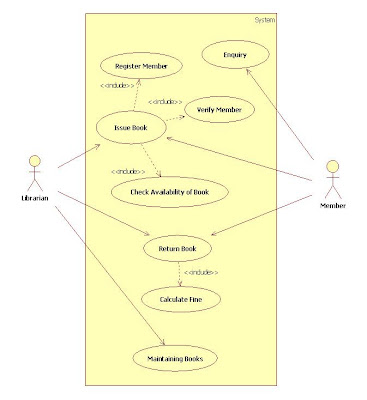
Unified Modelling Language Practicals. Below is the case study of it for the construction of different UML diagrams
CASE STUDY: Hospital Management System
Hospital management system helps in registering information about patients and handles patient’s query. A unique ID is generated for each patient after registration. This helps in implementing customer relationship management and also maintains medical history of patient. This system also monitors the doctor appointments, when the ID is generated the patient receives the appointment time and number from the receptionist and accordingly visit the doctor. This system also deals with testing appointments as and when ID is generated the patient receives the appointment time and number and accordingly undergoes the test.
It also deals with bed allotments to various patients by checking their ID. It also undergoes various operations by diagnosing the patients. The system identifies whether the person is a doctor or staff and handles various activities such as draw salary and give salary, also it adds doctor/staff information into database. This system is responsible for handling various other activities like deleting, editing doctor/staff information into the database. As per doctor diagnoses the patient, gives treatment and gives suggestions to patients and prescribe laboratory tests and medicines. This system also takes care of medical equipment, doctor visit, vitals recording, patient case sheet, diet ordering, blood requisition, transfer information and discharge information, maintenance of wards, inter and intrawards transfers also it generates patient’s discharge summary which includes patients health at the time of discharge, medical history, various diagnosis and drug prescriptions, history of patients illness and course in hospital. Patient can pay bill through credit card, cash or cheque whose information is maintained by this system.
Use Case Diagram:-
Activity Diagram:- Patient Payment
Activity Diagram:- Setting Doctor Appointment
Class Diagram:-
State Chart Diagram :- Patient
State Chart Diagram :- Doctor
State Chart Diagram:- Receptionist
Sequence Diagram:- Test Appointments
Sequence Diagram:- Bed Allotment
Collaboration Diagram:- Test Appointments
Collaboration Diagram:- Bed Allotments
Component Diagram:-
Deployment Diagram:-


