Saturday, 28 January 2017

Performance of Swarm Routing Protocol Under MANET

Caution :

If you try to use SWARM routing under highly mobile and try to send much data which will consume much bandwidth, then the performance of the SWARM routing will become very worst. Some of the papers that you see in literature may try to hide this fact.
Further, this evaluation is an elementary evaluation which considered only “time vs performance” as a metric. So any serious research on this routing protocol will need a lot of iterative simulations and more advanced analysis.

Important Sections of the Simulation Script

Some of the important parameters

01
02
03
04
05
06
07
08
09
10
11
12
13
14
15
16
17
18
19
20
21
22
23
24
25
26
27
28
29
30
31
32
33
34
35
set val(chan) Channel/WirelessChannel ;# channel type
set val(prop) Propagation/TwoRayGround ;# radio-propagation model
set val(ant) Antenna/OmniAntenna ;# Antenna type
set val(ll) LL ;# Link layer type
set val(ifq) Queue/DropTail/PriQueue ;# Interface queue type
set val(ifqlen) 50 ;# max packet in ifq
set val(netif) Phy/WirelessPhy ;# network interface type
set val(mac) Mac/802_11 ;# MAC type
set val(rp) [lindex $argv 0] ;# Change it as SWARM or AODV or DSR
set val(TotalNodes) 10
set val(xdim) 1000
set val(ydim) 500
set val(speed) 20 ;# Change it as SWARM or AODV or DSR
set val(StartTime) 0.00
set val(SimTime) 50.00
# unity gain, omni-directional antennas
# set up the antennas to be centered in the node and 1.5 meters above it
Antenna/OmniAntenna set X_ 0
Antenna/OmniAntenna set Y_ 0
Antenna/OmniAntenna set Z_ 1.5
Antenna/OmniAntenna set Gt_ 1.0
Antenna/OmniAntenna set Gr_ 1.0
# Initialize the SharedMedia interface with parameters to make
# it work like the 914MHz Lucent WaveLAN DSSS radio interface
Phy/WirelessPhy set CPThresh_ 10.0
Phy/WirelessPhy set CSThresh_ 1.559e-11
Phy/WirelessPhy set RXThresh_ 3.652e-10
Phy/WirelessPhy set Rb_ 2*1e6
#inital transmission power of all the nodes
Phy/WirelessPhy set Pt_ 0.2819;# Change it if required
Phy/WirelessPhy set freq_ 914e+6
Phy/WirelessPhy set L_ 1.0

Setting Node Configuration


01
02
03
04
05
06
07
08
09
10
11
12
13
14
15
$ns node-config -adhocRouting $val(rp) \
-llType $val(ll) \
-macType $val(mac) \
-ifqType $val(ifq) \
-ifqLen $val(ifqlen) \
-antType $val(ant) \
-propType $val(prop) \
-phyType $val(netif) \
#-channelType $val(chan) \
-topoInstance $topo \
-agentTrace ON \
-routerTrace ON \
-macTrace ON \
-movementTrace OFF \
-channel $chan_1

Creating Nodes and Settingup Some mobility


01
02
03
04
05
06
07
08
09
10
11
12
13
14
15
16
17
18
19
20
21
22
23
24
25
26
27
28
29
30
31
32
33
34
35
36
37
38
39
40
41
42
43
44
45
46
for {set i 0} {$i < [expr $val(TotalNodes) ] } {incr i} {
set node($i) [$ns node ]
$node($i) random-motion 1 ;# disable random motion
set tx [$rng integer [expr $val(xdim)-100]]
set ty [$rng integer [expr $val(ydim)-100]]
set tx [expr $tx + 50 ]
set ty [expr $ty + 50 ]
$node($i) set X_ $tx
$node($i) set Y_ $ty
$node($i) set Z_ 0.0
$node($i) color "black"
$ns initial_node_pos $node($i) 10
}
# set the position of the sender and reciever at two extreem ends
set x 100
set y [expr $val(ydim) - 100 ]
$node(0) set X_ $x
$node(0) set Y_ $y
$node(0) set Z_ 0.0
$ns initial_node_pos $node(0) 20
$ns at 0.0 "$node(0) setdest $x $y 20000.0"
$ns at 0.0 "$node(0) label Sender"
$ns at 0.0 "$node(0) color blue"
set x [expr $val(xdim) - 100 ]
set y 100
set n [expr $val(TotalNodes) -1 ]
$node($n) set X_ $x
$node($n) set Y_ $y
$node($n) set Z_ 0.0
$ns initial_node_pos $node($n) 20
$ns at 0.0 "$node($n) setdest $x $y 20000.0"
$ns at 0.0 "$node($n) label Reciever"
$ns at 0.0 "$node($n) color blue"
if {$val(speed) > 0 } {
for {set i 0} {$i < [expr $val(TotalNodes) ]} {incr i} {
set tx [$rng integer [expr $val(xdim)-100]]
set ty [$rng integer [expr $val(ydim)-100]]
set tx [expr $tx + 50 ]
set ty [expr $ty + 50 ]
$node($i) random-motion 1
$ns at 0.0 "$node($i) setdest $tx $ty $val(speed)"
}
}


Setting up some traffic

01
02
03
04
05
06
07
08
09
10
11
12
13
14
15
16
17
18
19
20
21
22
23
# Setup traffic flow between nodes
# CBR connections between node(0) and node(1)
set udp [new Agent/UDP]
$udp set class_ 2
set sink [new Agent/LossMonitor]
$ns attach-agent $node(0) $udp
$ns attach-agent $node([expr $val(TotalNodes) -1 ]) $sink
$ns connect $udp $sink
set cbr [new Application/Traffic/CBR]
$cbr set class_ 2
$cbr set packetSize_ 1024
$cbr set interval_ 0.05
$cbr attach-agent $udp
$ns at 0.002 "$cbr start"
$ns at $val(StartTime) "$cbr stop"
$ns at $val(SimTime).01 "stop"

Record Some Events for Performance Analysis

01
02
03
04
05
06
07
08
09
10
11
12
13
14
15
16
17
18
19
20
21
22
23
24
25
26
27
28
29
30
31
32
33
34
35
proc record {} {
global sink fpRecieved fpDropped fdTput fdLrate
#Get An Instance Of The Simulator
set ns [Simulator instance]
#Set The Time After Which The Procedure Should Be Called Again
set time 2.0
#How Many Bytes Have Been Received By The Traffic Sinks?
set npkts [$sink set npkts_]
set nbytes [$sink set bytes_]
set nlost [$sink set nlost_]
#Get The Current Time
set now [$ns now]
#Save Data To The Files
puts $fpRecieved "$now [expr $nbytes]"
puts $fdTput "$now [expr $nbytes/$time*8/1000000]"
if {$npkts> 0.0 } {
set lossrate1 [expr $nlost / $npkts ]
puts $fdLrate "$now $lossrate1"
} else {
puts $fdLrate "$now 0"
}
$sink set bytes_ 0
#Re-Schedule The Procedure
$ns at [expr $now+$time] "record"
}

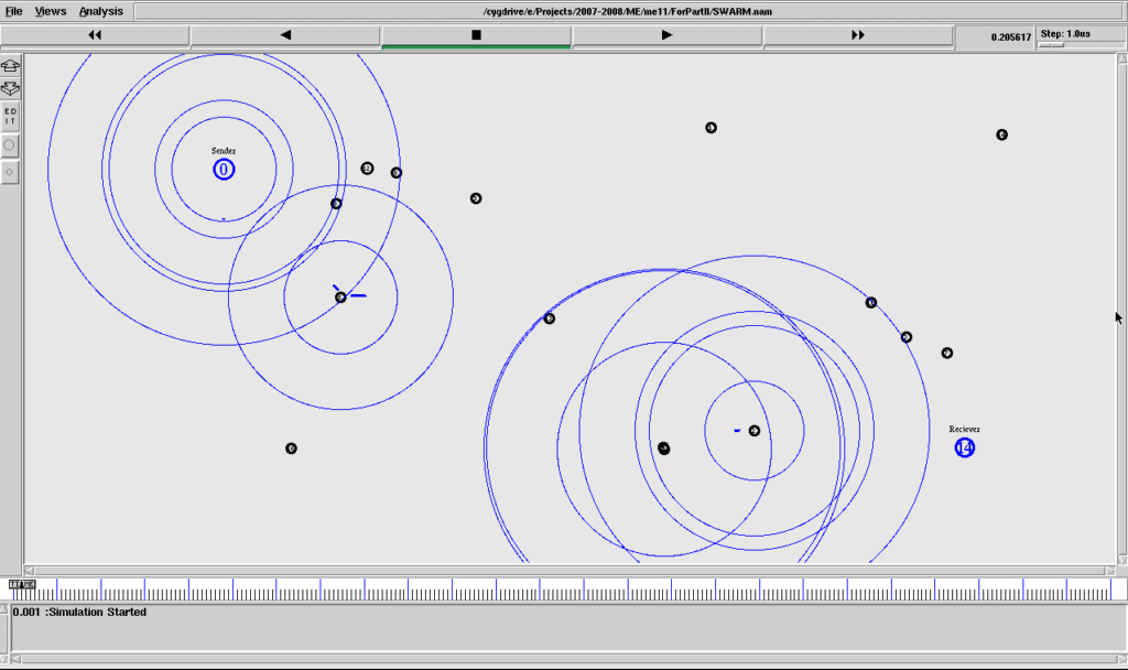
The Nam Outputs


Overall Results without Mobility

Average Received Packets over time

Average Loss Rate Over Time


Average Throughput Over Time

Without mobility, SWARM routing gave very good throughput

Loss rate is very very low in the case of SWARM and AODV while comparing it with DSR
Without mobility, the received bytes is high. The Graph is almost similar to throughput graph, but the x axis is showing total received bytes.

Overall results with Mobility 20m/sec

Average Received Packets over time


Average Received Packets over time

Average Throughput Over Time
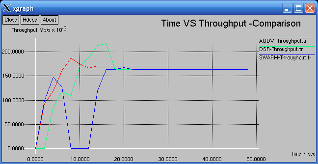
With mobility, the received bytes is almost equal in all the three protocols
With mobility, the Packet loss rate is low in the case of SWARM and AODV

Conclusion :

Without mobility and low rate of traffic (as in this experiment), SWARM routing performed good. But, with mobility, all the three protocols gave almost equal throughput. As I mentioned in the very first paragraph, if you try to use SWARM routing under highly mobile and try to send much data which will consume much bandwidth, then the performance of the SWARM routing will become very worst. Some of the papers that you see in literature may try to hide this fact.
So, if we use SWAM in a network without mobility (such as sensor network) and with suitably less traffic condition, then SWAM may compete some of the existing MANET routing protocols


What is background traffic in a network simulation?

A background traffic is nothing but another traffic which is used simultaneously along with the primary traffic of interest.
For example, if you need to evaluate the performance of your custom voice over IP (VoIP) application, then it may use tcp or sctp  to transport your voice. But in ideal network condition, you will have all the necessary network resources and bandwidth so that you can not prove that your VoIP application will work better even in worst network condition. So, for that, you have to simulate the worst network condition with some “bottle necks” and “traffic overheads”.  For that purpose, another traffic is needed – Such background traffic may use any kind of transport agent (tcp, udp, etc.,) and may use any kind of application (cbr, vbr, telnet, ftp, etc.,)
So, for example, if you need to evaluate the performance of your VoIP application protocol with respect to different network load condition, you may do it in different ways.0
(1) Run the simulation with different background traffic conditions (against 5, 10, 20, background cbr flows) and how your fixed number of VoIP flows getting affected by such background traffic condition.
(2) Or, without any such background traffic, simply you may run the simulation with different number of VoIP flows (5, 10, 20, .. VoIP flows) and evaluate its performance
Generally, researchers prefer combining (1) and (2) to do a good evaluation while evaluating their new protocol.

Sunday, 25 December 2016

DBMS :

Normalization

What is Normalization?
Normalization is the process of efficiently organizing
data in a database. There are two goals of the
normalization process: eliminating redundant data
(for example, storing the same data in more than one
table) and ensuring data dependencies make sense
(only storing related data in a table). Both of these
are worthy goals as they reduce the amount of space
a database consumes and ensure that data is
logically stored.

The Normal Forms:
The database community has developed a series of
guidelines for ensuring that databases are
normalized. These are referred to as normal forms
and are numbered from one (the lowest form of
normalization, referred to as first normal form or 1NF)
through five (fifth normal form or 5NF). In practical
applications, you'll often see 1NF, 2NF, and 3NF along with the occasional 4NF. Fifth normal form
is very rarely seen and won't be discussed in this article.
Before we begin our discussion of the normal forms, it's important to point out that they are
guidelines and guidelines only. Occasionally, it becomes necessary to stray from them to meet
practical business requirements. However, when variations take place, it's extremely important
to evaluate any possible ramifications they could have on your system and account for possible
inconsistencies. That said, let's explore the normal forms.

First Normal Form (1NF)
First normal form (1NF) sets the very basic rules for an organized database:
For more details, read Put t ing your Dat abase in First Normal Form

Second Normal Form (2NF)
Second normal form (2NF) further addresses the
concept of removing duplicative data:
Eliminate duplicative columns from the same table.
Create separate tables for each group of related data and identify each row with a unique
column or set of columns (the primary key).
of a table and place them in separate tables.
Create relationships between these new tables and
their predecessors through the use of foreign keys.

Third Normal Form (3NF)
Third normal form (3NF) goes one large step further:
Meet all the requirements of the second normal form.
Remove columns that are not dependent upon the primary key.

Boyce-Codd Normal Form (BCNF or 3.5NF)
The Boyce-Codd Normal Form, also referred to as the "third and half (3.5) normal form", adds
one more requirement:
Meet all the requirements of the third normal form.
Every determinant must be a candidate key.

Fourth Normal Form (4 NF)
Finally, fourth normal form (4NF) has one additional requirement:
Meet all the requirements of the third normal form.
A relation is in 4NF if it has no multi-valued dependencies.

Remember, these normalization guidelines are cumulative. For a database to be in 2NF, it must
first fulfill all the criteria of a 1NF database.

Meet all the requirements of the first normal form.
Remove subsets of data that apply to multiple rows

Data Communication & Networks:

Notes on Data Communication & Networks :Part II

Hello Friends!


Data Communication & Networks is one of the important subjects in UGC NET exam on which lots of questions are asked. So, prepare this subject well. The syllabus of the subject is vast, but is one of the easiest subjects to prepare. 

Please read the post and then post your comments/suggestions:

ETHERNET: Ethernet frames must carry a minimum payload of 46 bytes, which ensures that a valid Ethernet frame is 512-bits long (considering bits of header section also). The shortest Ethernet frame is 64 bytes in length, which carry Control messages.

Ethernet frames don't have a way to indicate end-of-frame, but an inter-frame gap (of time required to send 96 bit of data, i.e. 9.6 micro sec.) is used.

Horn antennas are very popular at UHF (300 MHz-3 GHz) and higher frequencies. They have a wide impedance bandwidth, implying that the input impedance is slowly varying over a wide frequency range.
S-parameters describe the input-output relationship between ports (or terminals) in an electrical system. A port can be defined as any place where we can deliver voltage and current.
Waveforms are not made up of a discrete number of frequencies, but rather a continuous range of frequencies (sum of frequencies).
Through modulation the waveforms can be relocated to separate frequency bands. Television is broadcast primarily at 54-216 MHz. FM radio operates between 87.5-108 MHz.
Frequency Band Name
Frequency Range
Wavelength (Meters)
Application
Extremely Low Frequency (ELF)
3-30 Hz
10,000-100,000 km
Underwater Communication
Super Low Frequency (SLF)
30-300 Hz
1,000-10,000 km
AC Power (though not a transmitted wave)
Ultra Low Frequency (ULF)
300-3000 Hz
100-1,000 km
Earth Mode Communications*
Very Low Frequency (VLF)
3-30 kHz
10-100 km
Navigational Beacons
Low Frequency (LF)
30-300 kHz
1-10 km
AM Radio
Medium Frequency (MF)
300-3000 kHz
100-1,000 m
Aviation and AM Radio
High Frequency (HF)
3-30 MHz
10-100 m
Shortwave Radio
Very High Frequency (VHF)
30-300 MHz
1-10 m
FM Radio
Ultra High Frequency (UHF)
300-3000 MHz
10-100 cm
Television, Mobile Phones, GPS
Super High Frequency (SHF)
3-30 GHz
1-10 cm
Satellite Links, Wireless Communication
Extremely High Frequency (EHF)
30-300 GHz
1-10 mm
Astronomy, Remote Sensing
Visible Spectrum
400-790 THz (4*10^14-7.9*10^14)
380-750 nm (nanometers)
Human Eye
* Communications through the ground using conduction fields e.g. military communications.

Slot Time: It is twice the time it takes for an electronic pulse to travel the maximum distance between two nodes. Thus Propagation delay takes half of the time of slot time since it is only the measure of the time required for signal to reach from node A to B. Slot time is used for half-duplex Ethernet network operation. It is 512 bit times for Ethernet networks operating below 1 Gbit/s, and 4096 bit times for Gigabit Ethernet. To reliably detect collisions, the minimum transmission time for a complete frame must be at least one slot time, whereas the round-trip propagation delay must be less than a slot time (half of slot time).

Back-off Algorithm: Once a collision is detected by simultaneous transmitters, they will follow a backoff algorithm, which requires each transmitter to wait an integral number of slot times (51.2 µs) before attempting a new transmission sequence. The integer is determined by the equation:
0<=r<2 power k where k = min (n, 10)
The variable k is actually the number of collisions capped at a maximum of 10. Therefore, r can range from 0 to 1023. The actual value for r is determined by a random process within each Ethernet node. As the number of consecutive collisions increases, the range of possible backoff times increases exponentially. The number of possible retries is max. 16.
There are no collisions with a full-duplex link, where each node is paired with a port on the hub.

Collision Domain - a section of a network where data packets can collide with one another when being sent on a shared medium or through repeaters, in particular.

The 5-4-3 rule: A system can have up to five segments in series, with up to four repeaters and no more than three mixing segments (a segment that may be connected to more than two transceivers).

The FCS field in Ethernet frame provides only bit-level error detection, no error recovery.

UDP is also known as laissez-faire protocol

TCP is used for unicast addresses only, so multicast applications must use the UDP transport protocol.

In asynchronous transmission, the Start bit always has a value of 0 (a Space). The Stop Bit always has a value of 1 (a Mark). This means that there will always be a Mark (1) to Space (0) transition on the line at the start of every word.

Application layer is free to send any size of data, there is no upper limit defined by standards. The lower layers divides the data if needed.
A channel with x bps may not necessarily transmit data at x rate, since protocols, encryption, and other factors can add may overheads.

The asymptotic bandwidth (formally asymptotic throughput) for a network is the measure of maximum throughput for a greedy source (a traffic generator that generates data at the maximum rate possible and at the earliest opportunity possible).

CIDR: Classless Inter-Domain Routing, known as supernetting, is a solution to limited address space problem in a network. It allocates address space to ISPs and end users on any address bit boundary, instead of on 8-bit segments (which is class based addressing). It appends to the IP address a slash character and the decimal number as routing prefix, e.g., "192.168.2.0/24" for IPv4, and 2001:db8::/32 for IPv6. The value after / indicates how many bits are used for the network prefix, leaving the remaining bits to identify the specific host.

CIDR currently uses prefixes anywhere from 13 to 27 bits. This solution fits an organization's specific needs. It helps in reducing number of entries in global routing tables. It is the concept of subnetting within the internet itself.

The industrial, scientific and medical (ISM) radio bands are radio bands (portions of the radio spectrum) reserved internationally for industrial, scientific and medical purposes other than communications. These are for unlicensed operations. Cordless phones, Bluetooth devices, near field communication (NFC) devices, and wireless computer networks all use frequencies allocated to low power communications as well as ISM.
Hartley's law- "The maximum data rate of a physical communication link is proportional to its bandwidth in hertz, which is sometimes called frequency bandwidth, spectral bandwidth, RF bandwidth, signal bandwidth or analog bandwidth."
A Baud Rate represents the number of bits that are actually being sent over the media, not the amount of data that is actually moved from one DTE device to the other. That means, baud rate decides the actual bit rate. For example, the bit rate is 9600
The Intelligent Network (IN) is the standard network architecture which allows telecom operators to differentiate themselves by providing value-added services in addition to the standard telecom services. The intelligence is provided by network nodes on the service layer (a conceptual layer within a network service provider architecture. It aims at providing middleware that serves third-party value-added services and applications at a higher application layer.)

The Internet protocol suite ( TCP/IP Model), occasionally known as the DoD model due to the foundational influence of the ARPANET. The TCP/IP model and related protocols are maintained by the Internet Engineering Task Force (IETF).

PORT: Each process that wants to communicate with another process identifies itself to the TCP/IP protocol suite by one or more ports. Application Layer talks with Transport layer through ports. A port number helps the transport layer protocols (like TCP) to know the type of content residing inside the packet.
A port is a 16-bit number, used by the host-to-host protocol to identify to which higher level protocol or application program (process) it must deliver incoming messages. There are two types of ports. Well-known port numbers(0-1023) are typically odd, because early systems using the port concept required an odd/even pair of ports for duplex operations.
The well-known ports are controlled and assigned by the Internet Assigned Number Authority (IANA) and on most systems can only be used by system processes or by programs executed by privileged users. Ephemeral ports are opposite to well-known ports. Such port number are used by clients and are contained in the UDP datagrams sent to the server.

Normally, a server will use either TCP or UDP, but there are exceptions. For example, domain name servers use both UDP port 53 and TCP port 53.

SOCKET: A socket is a special type of file handle, which is used by a process to request network services from the operating system. A socket address is the triple: <protocol, local-address, local-process>. For example, in the TCP/IP suite:
<tcp, 193.44.234.3, 12345>
An association is the 5-tuple that completely specifies the two processes that comprise a connection:
<protocol, local-address, local-process, foreign-address, foreign-process>. In the TCP/IP suite, the following could be a valid association:
<tcp, 193.44.234.3, 1500, 193.44.234.5, 21>
Two processes communicate via TCP sockets. The socket model provides a process with a full-duplex byte stream connection to another process.

UDP: UDP is basically an application interface to IP. It adds no reliability, flow-control, or error recovery to IP. It simply serves as a multiplexer/demultiplexer for sending and receiving datagrams, using ports to direct the datagrams. It requires the application to take responsibility for error recovery and so on.
Slow-start is one of the algorithms that TCP uses to control congestion inside the network. It is also known as the exponential growth phase.
Broadband means "having instantaneous bandwidths greater than 1 MHz and supporting data rates greater than about 1.5 Mbit/s." In telecommunication, Broadband refers to a communication bandwidth of at least 256 kbit/s. Each channel is 6 MHz wide.
The additive-increase/multiplicative-decrease (AIMD) algorithm is a feedback control algorithm used by  TCP for Congestion Avoidance. The approach taken is to increase the transmission rate (window size), probing for usable bandwidth, until loss occurs.
IP address classes:
Class
Leftmost bits
Start address
Finish address
A
0xxx
0.0.0.0
127.255.255.255
B
10xx
128.0.0.0
191.255.255.255
C
110x
192.0.0.0
223.255.255.255
D
1110
224.0.0.0
239.255.255.255
E
1111
240.0.0.0
255.255.255.255

IP address range for Intranets (Private Networks):

Class
Private start address
Private finish address
A
10.0.0.0
10.255.255.255
B
172.16.0.0
172.31.255.255
C
192.168.0.0
192.168.255.255

IP packets addressed by them cannot be transmitted onto the public Internet. If such a private network needs to connect to the Internet, it must use either a network address translator (NAT) gateway, or a proxy server.In IPV6, The address block fc00::/7 has been reserved for private networks.
IP officially reserves the entire range from 127.0.0.0 through 127.255.255.255 for loopback purposes.
IPv6 does not use classes. IPv6 supports the following three IP address types: unicast, multicast and anycast. IPv6 does not support broadcast. Multicast addresses in IPv6 start with 'FF' (255) just like IPv4 addresses. Unicast addresses have 3 defined scopes, including link-local, site-local and global; and multicast addresses have 14 scopes.
The number of IPv6 addresses is 1028. There is no ARP in V6. Currently, DHCP, FTP, PPP, RIP, SNMP, VPN, L2TP and Telnet do not support IPv6.
IPv6 does not require NAT. NAT, too, doesn't support V6. Currently, IPv6 packets are not forwarded.
IPv6 reserves just two special addresses: 0:0:0:0:0:0:0:0 and 0:0:0:0:0:0:0:1. IPv6 uses 0:0:0:0:0:0:0:0 internal to the protocol implementation, so nodes cannot use it for their own communication purposes. IPv6 uses 0:0:0:0:0:0:0:1 as its loopback address, equivalent to 127.0.0.1 in IPv4. The minimum size of an IP datagram is 28 bytes, including 20 bytes of header.
BIND and NSD are the most widely used DNS software on the Internet
Anycast is a network addressing and routing methodology in which datagrams from a single sender are routed to the topologically nearest node in a group of potential receivers, though it may be sent to several nodes, all identified by the same destination address. On the Internet, anycast is usually implemented by using BGP.
In denial-of-service attacks, a rogue network host may advertise itself as an anycast server for a vital network service, to provide false information or simply block service.
"6 to 4" is an Internet transition mechanism for migrating from IPv4 to IPv6, a system that allows IPv6 packets to be transmitted over an IPv4 network. 6to4 does not facilitate interoperation between IPv4-only hosts and IPv6-only hosts, but simply a transparent mechanism used as a transport layer between IPv6 nodes.
The network requests supporting DNS lookups run over TCP and UDP, port 53 by default.

SDE

Software Design Engineering

Coupling/Cohesion

 Software Design

  • Software design is a creative process, just like designing anything else
  • To see a wrong design, we can check with the requirements in the analysis model
  • To see a bad design, we need to assess the design model and analyse the components, whether the performance can be improved by changing the modules or the interfaces
         In Analysing the software Design many factors are used, such as Coupling, Cohesion, Factoring, System Shape, etc.

 Coupling

  • The degree of interdependence between two modules”
  • We aim to minimise coupling - to make modules as independent as possible
    Low coupling can be achieve by:
  • eliminating unnecessary relationships
  • reducing the number of necessary relationships
  • easeing the ‘tightness’ of necessary relationships

Types of Coupling

  • Data coupling       (Most Required)   
                               
  • Stamp coupling
     
  • Control coupling
     
  • Hybrid coupling
     
  • Common coupling
     
  • Content coupling  (Least Required)

Data Coupling 

  • Modules communicate by parameters
     
  • Each parameter is an elementary piece of data
     
  • Each parameter is necessary to the communication
     
  • Nothing extra is needed

Data coupling problems

  • Too many parameters - makes the interface difficult to understand and possible error to occur
     
  • Tramp data - data ‘traveling’ across modules before being used

Stamp coupling

  • A composite data is passed between modules
     
  • Internal structure contains data not used
     
  • Bundling - grouping of unrelated data into an artificial structure

Control coupling

  • A module controls the logic of another module through the parameter
     
  • Controlling module needs to know how the other module works - not flexible!

Hybrid coupling

  • A subset of data used as control
     
  • Example: account numbers 00001 to 99999
  • If 90000 - 90999, send mail to area code of last 3 digit (000 - 999)

Common coupling

  • Use of global data as communication between modules
     
  • Dangers of
  • ripple effect
     
  • inflexibility
     
  • difficult to understand the use of data

Content coupling

  • A module refers to the inside of another module
     
  • Branch into another module
     
  • Refers to data within another module
     
  • Changes the internal workings of another module
     
  • Mostly by low-level languages


Cohesion

  • “The measure of the strength of functional relatedness of elements within a module”
     
  • Elements: instructions, groups of instructions, data definition, call of another module
                                                                                                   
  • We aim for strongly cohesive modules
  • Everything in module should be related to one another - focus on the task
     
  • Strong cohesion will reduce relations between modules - minimise coupling

      Types of Cohesion

  • Functional cohesion (Most Required)
     
  • Sequential cohesion
     
  • Communicational cohesion
     
  • Procedural cohesion
     
  • Temporal cohesion
     
  • Logical cohesion
     
  • Coincidental cohesion (Least Required)

Functional cohesion

  • All elements contribute to the execution of one and only one problem-related task
     
  • Focussed - strong, single-minded purpose
     
  • No elements doing unrelated activities
  • Examples of functional cohesive modules:
  • Compute cosine of angle
     
  • Read transaction record
     
  • Assign seat to airline passenger

Sequential cohesion

  • Elements are involved in activities such that output data from one activity becomes input data to the next
     
  • Usually has good coupling and is easily maintained
     
  • Not so readily reusable because activities that will not in general be useful together
     
  • Example of Sequential Cohesion
     
  • module format and cross-validate record
     
  •    use raw record
     
  •     format raw record
     
  •    cross-validate fields in raw record
     
  •    return formatted cross-validated record
                 end module

Communicational Cohesion

  • Elements contribute to activities that use the same input or output data
     
  • Not flexible, for example, if we need to focus on some activities and not the others
     
  • Possible links that cause activities to affect each other
     
  • Better to split to functional cohesive ones
     
  • Example of Communicational Cohesion
     
  • module determine customer details
     
  •    use customer account no
     
  •    find customer name
     
  •    find customer loan balance
     
  •    return customer name, loan balance
end module
 

Procedural cohesion

  • Elements are related only by sequence, otherwise the activities are unrelated
     
  • Similar to sequential cohesion, except for the fact that elements are unrelated
     
  • Commonly found at the top of hierarchy, such as the main program module
     
  • Example of Procedural Cohesion
  • module write read and edit something
  •    use out record
     
  •    write out record
     
  •    read in record
     
  •    pad numeric fields with zeros
     
  •    return in record
         end module

Temporal cohesion

  • Elements are involved in activities that are related in time
     
  • Commonly found in initialisation and termination modules
     
  • Elements are basically unrelated, so the module will be difficult to reuse
     
  • Good practice is to initialise as late as possible and terminate as early as possible
     
  • Example of Temporal Cohesion
  • module initialise
  •    set counter to 0
     
  •    open student file 
     
  •    clear error message variable
     
  •    initialise array
       end module
 

Logical cohesion

  • Elements contribute to activities of the same general category (type)
     
  • For example, a report module, display module or I/O module
     
  • Usually have control coupling, since one of the activities will be selected
     
  • Example of Logical Cohesion
  • module display record
      use record-type, record
      if record-type is student then
             display student record
      else if record-type is staff then
             display staff record
end module
 

Coincidental cohesion

  • Elements contribute to activities with no meaningful relationship to one another
     
  • Similar to logical cohesion, except the activities may not even be the same type
     
  • Mixture of activities - like ‘rojak’!
     
  • Difficult to understand and maintain, with strong possibilities of causing ‘side effects’ every time the module is modified
  • Example of Coincidental Cohesion
module miscellaneous functions
   use customer record
   display customer record
   calculate total sales
   read transaction record
   return transaction record
end module
 
Determining Module Cohesion


Other Design Factors to Consider
  • Factoring: reduce module size, clarifying system,minimise duplication of code, separating work from management, creating useful modules, simplifying
     
  • System Shape (Structure)
     
  • Redundancy
     
  • Fan-in/Fan-out
     
  • Restrictivity/Generality

DBMS

DBMS Notes Series-1

Hello Friends!

Let's discuss questions on DBMS from previous year papers. To begin with, some of the multiple choice type questions are listed below:


Q. Location transparency allows :

 I. Users to treat the data as if it is done at one location.
 II. Programmers to treat the data as if it is at one location.
 III. Managers to treat the data as if it is at one location.
 Which one of the following is correct ?
 (A) I, II and III (B) I and II only (C) II and III only (D) II only

The right answer is (A). 

Reason: Location transparency means the location of data must not matter to the person who accesses/manipulates the data. This is a feature of distributed databases, which applies to every kind of database user. According to a definition on Wikipedia, "The location of a resource doesn't matter to either the software developers or the end-users. This creates the illusion that the entire system is located in a single computer, which greatly simplifies software development."

The I and II are database users. The III is a component of distributed databases. Database Manager components are responsible for providing seamless data access to users without regards to its location. Hence, this covers all 3 choices.


Q. Which of the following is correct?

I. Two phase locking is an optimistic protocol.
II. Two phase locking is pessimistic protocol
III. Time stamping is an optimistic protocol.
IV. Time stamping is pessimistic protocol.

(A) I and III (B) II and IV (C) I and IV (D) II and III


The right answer is (D).

Reason: Optimistic Vs. Pessimistic approach: The optimistic concurrency control approach doesn't actually lock anything. It is based on the assumption that conflicts of database operations are very less. Means, when when oner transaction is executing, other transactions will not access the same data item being accessed by the executing one. It lets transactions run to completion and only checks for conflicts when they are about to commit. Thus, a transaction is executed without any restrictions until it is committed.

The pessimistic approach believes that some other transaction might try to access the same piece of data. So, in order to prevent any conflict, a transaction will first acquire all the required locks, then perform all the operations. It has two phases:

1. Growing Phase, where a transaction must first acquire all the locks.
2. Shrinking Phase, where a transaction releases all the locks one-by-one.(It cannot issue lock requests here.)

Q. Data warehousing refers to
(A) storing data offline at a separate site (B) backing up data regularly
(C) is related to data mining (D) uses tape as opposed to disk


The right answer is (C)
Reason: NOT A because: Not all data of Data warehouse stored offline as it depends on nature and usage of data.
NOT B because: A data warehouse typically stores a lot of historical data, that is often not subject to change. Data that does not change only needs to be backed up once.
NOT D because: Data may be stored using a proper mix of disks, tapes, or near-line storage.

Common data warehouse models include a data warehouse that is subject oriented, time variant, non-volatile, and integrated.


Q. The "PROJECT' operator of a relational algebra creates a new table that has always
(A) More columns than columns in original table
(B) More rows than original table
(C) Same number of rows as the original table
(D) Same number of columns as the original table

The right answer is (A) 
Reason: The number of tuples in the result of PROJECT  <list> (R) is always less or equal to the number of tuples in R.

Now, a few questions with descriptive answers:


Q. Show that 2-phase locking ensures serializability?


A. In databases and transaction processing two-phase locking, (2PL) is a concurrency control method that guarantees serializability. A transaction is said to follow the two-phase locking protocol if all locking operations (read_lock, write_lock) precede the first unlock operation in the transaction. Such a transaction can be divided into two phases:


Phase 1: Growing Phase

i)  transaction may obtain locks
ii)  transaction may not release locks

Phase 2: Shrinking Phase

i)  transaction may release locks
ii)  transaction may not obtain locks

If lock conversion is allowed, then upgrading of locks (from read-locked to write-locked) must be done during the expanding phase, and downgrading of locks (from write-locked to read-locked) must be done in the shrinking phase. Hence, a read_lock(X) operation that downgrades an already held write lock on X can appear only in the shrinking phase.


The protocol assures serializability. It can be proved that the transactions can be serialized in the order of their lock points  (i.e. the point where a transaction acquired its final lock). Two-phase locking does not ensure freedom from deadlocks.


Q. How to determine candidate key(s) for a relation?

A. Finding candidate keys is just as simple as applying some algorithm here and there.

In the first example, there are five attributes:
W H O S E
WH -> S
HOS -> E
Steps:
1. Find the attributes that are neither on the left and right side
> (none)
2. Find attributes that are only on the right side
> E
3. Find attributes that are only on the left side
> WHO
4. Combine the attributes on step 1 and 3
> since step 1 has no attributes, it’s just WHO
5. Test if the closures of attributes on step 4 are all the attributes
> in this case, it is true. Because with WH we can get S, and by HOS, we can get E.
So we have only one candidate key that is WHO.

Q. What are steps of a Database design?


A. Major Steps in Database Design are:
  1. Requirements Analysis: Talk to the potential users! Understand what data is to be stored, and what operations and requirements are desired.
  2. Conceptual Database Design: Develop a high-level description of the data and constraints (we will use the ER data model)
  3. Logical Database Design: Convert the conceptual model to a schema in the chosen data model of the DBMS. For a relational database, this means converting the conceptual to a relational schema (logical schema).
  4. Schema Refinement: Look for potential problems in the original choice of schema and try to redesign.
  5. Physical Database Design: Direct the DBMS into choice of underlying data layout (e.g., indexes and clustering) in hopes of optimizing the performance.
  6. Applications and Security Design: It defines how the underlying database will interact with surrounding applications.
Q. Differentiate b/w Specialisation and Generalisation in ER Model?

A. Specialisation:

Top-down design process; we designate subgroupings within an entity set that are distinctive from other entities in the set.
These subgroupings become lower-level entity sets that have attributes or participate in relationships that do not apply to the higher-level entity set.
Depicted by a triangle component labeled ISA (E.g. customer “is a” person).
Attribute inheritance – a lower-level entity set inherits all the attributes and relationship participation of the higher-level entity set to which it is linked.

Generalisation:

A bottom-up design process – combine a number of entity sets that share the same features into a higher-level entity set.
Specialization and generalization are simple inversions of each other; they are represented in an E-R diagram in the same way.
The terms specialization and generalization are used interchangeably.